Exploring the many carbon capture options
It has been more than 10 years since the first commercial carbon dioxide (CO2) capture and sequestration system motivated by greenhouse gas reduction was placed into service. In 1991, Norway became the world’s first country to impose a tax on CO2 emissions from point sources, to the tune of $55/ton. Five years later, Statoil began injecting CO2 beneath the bottom of the North Sea to avoid the stiff carbon tax. Today, the state-owned firm is injecting about a million tons of CO2 per year, in the process saving about $55 million a year in taxes. That’s a pretty good ongoing return on an $80 million investment.
In North America, EnCana’s Weyburn, Sask., field tertiary oil-recovery project dwarfs all similar sequestration projects. The CO2 by-product of the Great Plains Synfuels Plant in North Dakota is collected and transported north to an oil field in Saskatchewan through a 200-mile pipeline and injected underground, extending the field’s productive life (Figure 1). The CO2 acts much like a solvent, removing oil trapped in cracks of reservoir rock. In Saskatchewan, the results have been impressive: a two-thirds increase in oil production from the field since CO2 flooding began in 2000. The project is expected to permanently store 20 million tons of CO2 over its lifetime.
|
1. Before sequestration. The typical process for injecting CO2 into a depleted oil field to increase its output. Source: IMTE AG Consulting Engineers
|

The differences between these two projects go well beyond their technical details and original motivations. The current U.S. plan for carbon capture and sequestration lies somewhere between Norway’s top-down regulatory approach and the free-market partnership between Weyburn and Great Plains Synfuels. Washington envisions meeting the carbon challenge with government-industry partnerships seeded by federal money that industry would match.
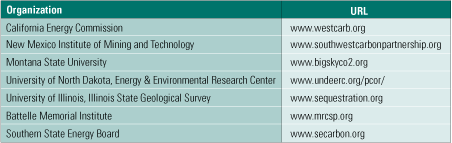
In the U.S., there are seven regional carbon sequestration partnerships spanning 40 states (Table 1), and they are poised to scale up their research and pilot plant operations as the third phase of a multidecade effort. The partnerships spent much of 2003–2005 characterizing the regional opportunities for capture and storage of CO2 in North America and publishing the National Carbon Sequestration Atlas and Geographic Information System and other materials. Phase 2 began in 2005 with field evaluations that will continue through 2009. Phase 3 is the deployment phase; several high-volume (up to 1 million tons/year) sequestration pilot projects are scheduled to be built in North America between now and 2016.
|
Table 1. Regional carbon sequestration partnerships. Source: U.S. EPA

|
The U.S. Department of Energy (DOE) sequestration program is funding a diverse portfolio of around 70 different R&D projects with a projected 2007 budget of around $74 million. Many of the projects enjoy strong industry support; the private sector is providing 39% of their funding, on average. U.S. investment in the sequestration R&D program to date is on the order of $260 million.
First things first
Over the past 160 years, atmospheric levels of CO2 have risen from around 280 ppm to 360 ppm. The increase has been caused primarily by skyrocketing growth in the combustion of fossil fuels by vehicles, factories, and power plants. Predictions of global energy use this century suggest continued increases in carbon emissions and atmospheric concentrations of CO2 unless major changes are made in the ways we produce and use energy, and in how we manage carbon.
In the U.S., power generation accounts for about one-third of national, man-made CO2 emissions. Creating a power plant that emits no carbon (the goal of DOE’s FutureGen effort) will require the simultaneous development of carbon capture and sequestration technologies. Sequestration projects such as the ones in Norway and the U.S. described above will be only marginally useful unless the tonnage of CO2 emitted by power plants can be reduced considerably. Likewise, a CO2-capturing integrated gasification combined-cycle (IGCC) plant without a place to safely store the gas will accomplish just as little.
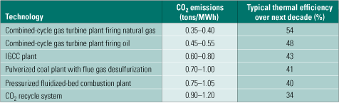
State-of-the-art conventional generation technologies are still growing in thermal efficiency, and we could see a further improvement of 4% to 5% over the next decade or so (Table 2). New alloys being developed for ultrasupercritical boilers, and steam turbines may push the efficiency of plants based on them to 50% to 52% by 2020, and to 52% to 55% by 2050. Table 2 also lists the range of CO2 emissions for each of the power generation technologies considered.
|
Table 2. CO2 emissions of various power generation systems. Source: IMTE AG Consulting Engineers
|
Many CO2 capture options
Power engineers would be wise to gain a understanding of the growing role that coal gasification in general, and IGCC in particular, will play in clean electricity production worldwide over the next decade. At present, it appears that the carbon-capture portion of future IGCC plants will be based on one of four general technological approaches:
- Postcombustion CO2 capture
- Oxy-fuel combustion
- Precombustion decarbonization
- A potpourri of novel concepts that resist categorization
Each technology has advantages and disadvantages. Some have been proven in the chemicals production industry; others, though holding much future promise, are still in the laboratory development stage. The remainder of this article explores these four categories in greater detail.
Postcombustion CO2 capture
The first approach—the simple addition of a separate postcombustion CO2-capture system to a power plant—is the most straightforward technique. End-of-pipe treatment of flue gases produced by conventional fossil fuel–fired plants belongs in this category.
However, the technique’s economic efficiency is rather low. The huge volumes of flue gas containing relatively little CO2 must be handled by conventional absorption processes requiring very large and expensive equipment. What’s more, the efficiency penalty that the technique imposes on the power plant is huge, on the order of 25% to 35%. Yet postcombustion capture seems eminently suitable for the retrofitting of existing facilities because it does not affect the upstream (fuel) part of the plant.
Many commercial technologies being proposed for CO2 capture are not new and have proven effective as components of industrial processes. Many of those processes are technologically mature and available. For example, chemical and physical absorption are ready to CO2 capture in bulk quantities today—but at a prohibitive cost. R&D studies suggest that chemical absorption may be more suitable than physical absorption for postcombustion decarbonization. Physical absorption may be a better fit with precombustion decarbonization—the third technology approach (more on this later).
Pros and cons of amines. Alkanolamines are considered by many as the best candidates for postcombustion decarbonization of flue gases. They have been well proven well as decarbonization solvents in the gas processing, chemicals, and petroleum industries for more than 50 years.
Figure 2 is a flow diagram of a typical process of this sort. The upstream absorption stage cools the CO2 stream and removes particulates from it. Next, the cooled and cleaned stream enters the absorption tower, where it makes contact with the alkanolamine solvent in countercurrent flow. The gas to be absorbed enters the absorber at its bottom, flows up, and leaves at the top. The solvent enters the top of the absorber, flows down, and emerges at the bottom. CO2 is chemically bound to the solvent by the exothermic reaction of the gas with the amine in the solvent.
|
2. After-the-fact approach. The process flow of a typical flue gas decarbonization system. Source: IMTE AG Consulting Engineers
|
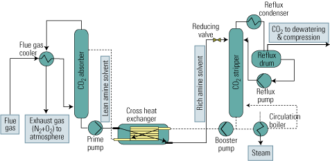
The liquid amine CO2-rich solvent then leaves the bottom of the absorber and passes into the stripping tower via a cross heat exchanger. In the CO2 stripper, the mixture is heated with steam to liberate the CO2 from the solvent as the acid gas. This step is carried out at lower pressure than the previous absorption step, to enhance desorption of CO2 from the liquid.
The CO2 is now ready for the further steps of compression, transport from the power plant to a storage site, and sequestration. The hot lean amine solution then flows through the cross heat exchanger, where it is contacted with the rich amine solution from the absorber. The lean amine solution from the cross heat exchanger is then returned to the top of the absorption tower.
Amine absorption has been practiced at large scale in the natural gas processing industry to remove hydrogen sulfide (H2S) and CO2 from the fuel. Adapting the technique to flue gas decarbonization is problematic, for two reasons. First, CO2 is present in large quantities in flue gas, but H2S is only an impurity to be removed from natural gas. Second, decarbonization of natural gas must address the presence of H2S—but there is no H2S in flue gas.
The greatest obstacle to postcombustion decarbonization is the low pressure (atmospheric) of the flue gas. Only chemical solvents with high reaction energies like alkanoamines can economically scrub CO2 under such low partial pressures.
The term "amine" refers to group of organic compounds that can be derived from ammonia (NH3) by replacing one or more H2 molecules by organic radicals. Amines are classified according to the number of hydrogen atoms replaced.
Primary amines (RNH2) include monoethanol amine (MEA) and diglycolamine (DGA). There is considerable industrial experience with primary amine chemical absorption solvents, especially with MEA.
MEA, one of the most frequently used solvents for CO2 capture, has been the traditional solvent of choice for CO2 absorption and acid gas removal in general. It is the cheapest technique, but it generates the most reaction heat: 1.9 MJ/kg. Because MEA’s molecular weight is the lowest of the primary amines, it has the highest theoretical absorption capacity. But it also has the lowest boiling point, so there may be solvent carryover in the CO2 removal and regeneration steps. Another drawback of MEA is its high reactivity with carbon oxysulfide (COS) and carbon disulfide (CS2), which degrades the solvent. In addition, the CO2 itself is a strong corrosive agent.
Techniques based on primary amines have been used in industry. An example is the Fluor Daniel Econamine FG process, which uses MEA concentrations of around 30% by weight to successfully remove 80% to 90% of the CO2 from the flue of an ABB Lummus process. In the latter process, the MEA concentration is around 20% by weight.
Secondary amines (R2NH) include diethanolamine (DEA) and di-isopropylamine (DIPA). Secondary amines have lower capture reaction heat and enjoy some advantages over primary amines. For example, the reaction heat of CO2 with DEA is only 1.5 MJ/kg, compared with 1.9 MJ/kg for primary amines. This makes the use of secondary amines more economical in the regeneration step than using MEA. However, secondary amines share the other downsides of primary amines.
Tertiary amines (R3N) amines—including triethanolamine (TEA) and methyl-diethanolamine (MDEA)—are even less reactive. They require the least heat to liberate the CO2 from the solvent. For example, MDEA’s capture reaction heat is just 1.3 MJ/kg.
Because tertiary amines react more slowly with CO2, they must be circulated more quickly than primary and secondary amines. On the upside, tertiary amines degrade and corrode more slowly than primary and secondary amines.
Oxy-fuel combustion
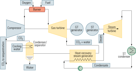
The second approach to carbon capture is oxy-fuel combustion, which also is called oxy-fuel decarbonization or O2/CO2 firing. It is a much more elegant technique than postcombustion CO2 capture because pure oxygen is used as the oxidant instead of air. Nitrogen is completely eliminated from the process. Instead of nitrogen, CO2 recycled in a semi-closed cycle serves as the working fluid (Figure 3, top).
|
3. More options. Oxy-fuel and precombustion options for power plant CO2 capture and sequestration. Source: IMTE AG Consulting Engineers

|
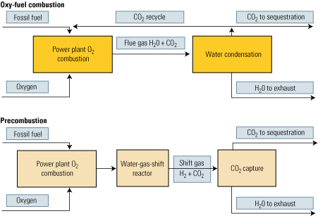
Oxy-fuel combustion is much more promising for new installations than postcombustion CO2 capture. Although the air separation (oxygen generation) unit consumes a lot of energy, its overhead is mitigated by the elimination of the need for final CO2 separation—the technique’s biggest plus. CO2 is produced in a high sequestration-ready concentration in the range of 80% to 98%. Water alone must be removed from the flue gas, by simple condensation.
There is a broad, ongoing, and worldwide R&D effort to reduce the cost of oxygen generation. Most of the advanced processes being investigated are based on operating membranes at high temperatures.
Small-scale test rigs have confirmed that overall plant efficiency and economics can be improved by oxy-fuel combustion. Larger-scale work is being done in glass and steel-melting furnaces. At this point, it appears that oxy-fuel combustion could be retrofitted to existing steam power plants without incurring exorbitant costs.
Figure 4 illustrates how oxy-fuel combustion could be incorporated into a combined-cycle cycle to enable carbon capture. The key elements of this process are:
- An air separation/oxygen generation unit (not shown).
- A gas turbine designed to operate with a CO2/H2O working fluid.
- A control system for maintaining stoichiometry between the streams of fuel and oxygen injected into the combustion chamber. Doing so is necessary to keep unreacted fuel and oxygen from reaching downstream of the chamber.
- A Rankine cycle circuit.
- A condenser/separator, for segregating the carbon dioxide from the water.
- A compressor/pumping/heat exchanger system, needed to pump the CO2 to its final destination.
|
4. Semi-tough. One possible way to retrofit a combined-cycle plant with an oxy-fuel combustion system that circulates CO2 in a semi-closed loop. Source: IMTE AG Consulting Engineers
|
For power plants fueled by natural gas, this concept would represent another alternative to precombustion capture. The only problem with implementing the scheme: It would be harder to operate the gas-fueled gas turbines with a CO2 working fluid than it would be for turbines firing a hydrogen-rich fuel. Accordingly, retrofitting existing gas-fired combined-cycle plants with an oxy-fuel system would not be economic because the turbines would have to be redesigned. Greenfield projects, by contrast, may indeed prove more feasible.
Precombustion decarbonization
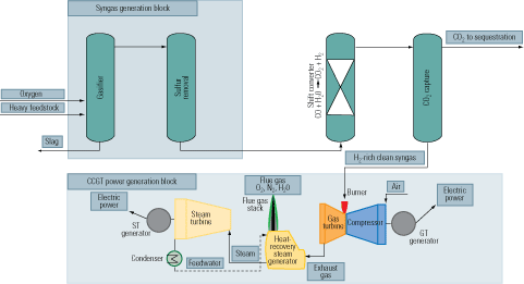
Removal of the carbon prior to the combustion stage of an IGCC plant is our third carbon-capture option (Figure 3, bottom). First, a fossil fuel is transformed into a synthetic gas (syngas), essentially a mixture of carbon monoxide (CO) + hydrogen (H2). Next, the CO in the syngas is converted to H2 + CO2 by a water-gas-shift (WGS) reactor. Finally, the CO2 is separated by conventional methods.
The big advantage of precombustion carbon removal is that the CO2 separation step consumes much less energy than in other processes because it takes place in a smaller reaction volume and at lower volumetric flow rates, elevated pressure, and higher component concentration. The higher concentrations make the capture process far less energy-intensive. The energy generation penalty, typically 10% to 16%, is roughly half that of postcombustion CO2 capture.
Precombustion carbon capture is a lot more cost-effective than postcombustion capture and slightly more effective than oxy-fuel capture. Technologies for precombustion capture of CO2 via gasification are well established in the process industries. They can be considered a segment of H2 production processes commonly used and proven in NH3 production, oil refining, and methanol synthesis. Figure 5 is a simplified flow diagram of an IGCC system, firing a heavy fuel feedstock, integrated with precombustion carbon capture.
|
5. Heavy duty. A flow diagram of an IGCC plant with a heavy fuel feedstock. Source: IMTE AG Consulting Engineers
|
An advantage of precombustion capture is that the syngas produced as the first step of the process can be used as fuel in a turbine cycle. Doing so would produce a flue gas stream high enough in CO2 concentration to allow the use of simple, inexpensive separation techniques. Figure 6 is similar to Figure 5, but it shows the syngas generation options that would be available to an IGCC plant using natural gas as feedstock. Commercial gas turbines are optimized to burn either natural gas or fuel oil. Tailoring them to burn hydrogen would certainly require a redesign, but it might not be substantial.
|
6. Lighter fare. A flow diagram of an IGCC plant firing natural gas and equipped for precombustion capture of CO2. Source: IMTE AG Consulting Engineers
|
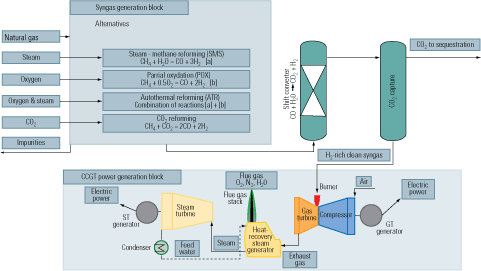
When natural gas is the feedstock, syngas can be produced by either of the technologies shown in Figure 5. The CO is reacted with steam in a catalytic process of the WGS reaction to produce CO2 and the highest possible amount of H2. Following the conversion and the removal of condensate, the gas mainly consists of H2 with CO2. The CO2 can then be separated by chemical or physical absorption and disposed of or put to use. The H2 can be used as chemical feedstock or as fuel for a combined-cycle plant or a fuel cell.
Chemical vs. physical solvents
Chemical or physical gas absorption equipped with a stripping regeneration stage—generally called cold gas cleanup (CGC)—is used for syngas desulfurization by all currently operating IGCC plants, with the sole exception of the Piñon Pine Power Project (funded by the DOE and Sierra Pacific Power Co.) in Nevada. Elevated pressures and relatively high concentration of CO2 in the syngas are the prime cost drivers for precombustion carbon removal technologies. Moreover, strong-affinity chemical solvents have to be used to capture such small concentrations of CO2 in such a big volume.
Absorption of CO2 by MDEA is very efficient. Unfortunately, the stronger the capture, the more heat is required to release the CO2 in the regeneration stage. Apart from this disadvantage, strong chemical degradation sensitivity to SO2 and NO2 exists. In the presence of oxygen, corrosion also becomes more aggressive.
Despite these drawbacks, the commercial use of the alkanolamine MDEA is currently popular at IGCC plants. Projects such as Plaquemine (1986), Wabash River (1995), Tampa Electric Polk (1996), Puertollano (1997), ISAB Energy (2000), Motiva Delaware (2000), and Piemsa (2006) employ MDEA for the same reason: It is highly effective at removing sulfur from syngas.
Of course, this does not mean that MDEA will retain its edge over physical solvents. Preliminary experience suggests that physical solvents may be more effective for this purpose.
Physical solvents
If the CO2 concentration and pressure could be increased, the CO2 capture equipment would be smaller and physical solvents could be used, with lower energy penalties for regeneration. Using physical solvents, CO2 concentration can be three times higher while pressure upstream of the gas turbine is typically 20 times higher. Volume concentration of the CO2 is therefore 60 times higher, compared with typical flue gas from a coal plant. The advantage in this case is lower heat consumption in the solvent regeneration step: No additional heat is necessary, and the stripping is driven mainly by the pressure release (flash distillation).
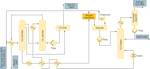
Rectisol. The Rectisol process with intermediate water-gas-shift is one of the most effective procedures for precombustion CO2 capture from IGCC plants firing a heavy fuel. It offers multiple benefits such as desulfurization, additional H2 generation via WGS, H2 separation, and CO2 capture—all in a single, integrated train.
This process configuration has been applied in the Pernis refinery/127-MW IGCC project operated by Shell Gasification Solutions. The Pernis plant, in the Netherlands, is the first IGCC facility equipped with CO2 separation, although the separated CO2 is currently vented. Thanks to this arrangement, Pernis could be considered the only sequestration-ready IGCC plant in the world.
Single-circuit Rectisol processes also are running at the 350-MW Vresova IGCC project in the Czech Republic and at Global Energy Inc.’s Schwarze Pumpe station in Germany.
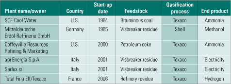
Selexol. Selexol is another physical solvent competitive with Rectisol. There are 55 Selexol operating units in syngas and natural gas service in the world. In operating IGCC plants, Selexol isn’t as popular, however. On the other hand, if H2 production or CO2 capture is the priority, Selexol moderately outperforms Rectisol. Table 3 lists the IGCC projects (principally at refineries) currently using Selexol. Figure 7 is a flow diagram of the process being used at Farmland Industries Inc.’s ammonia plant in Coffeyville, Kan.
|
Table 3. Gasification projects currently using Selexol. Source: IMTE AG Consulting Engineers
|
|
7. Selexol selected. The process flow at Farmland Industries’ ammonia plant in Coffeyville, Kan. The plant uses Selexol to treat syngas. Source: IMTE AG Consulting Engineers

|
Emerging concepts
The fourth and last category of carbon capture technologies comprises novel concepts based on techniques at the pilot or laboratory stage of development. Processes that use membranes, chemical looping, or hydration to separate CO2 are examples of these promising (in the longer term) technologies.
Ion transport membranes (ITMs). ITMs can selectively move oxygen ions and thus separate oxygen from any gas mixture. Ion transport is a very economical but very energy-intensive cryogenic process that uses ceramic, nonporous, mixed-conducting membrane media. The membrane itself uses conductors made of mixed-metal oxides.
The membrane conductivity state is initialized at high excitation temperatures, typically 800C to 900C. At these temperatures the ITMs exhibit both electric and oxygen ion conductivity. In stoichiometric terms, they are oxygen-deficient and thus create oxygen vacancies in their crystal lattice. The ion transport mechanism is based on the principle of ionic exclusion. First, oxygen from the air adsorbs on the surface of the membrane. The membrane then dissociates, ionizes, and releases electrons.
The oxygen anions occupy vacancies in the lattice and diffuse through the membrane, driven by an oxygen chemical-potential gradient. This gradient is proportional to the difference between the respective oxygen partial pressures on opposite sides of the membrane. At the permeate surface of the membrane, the oxygen ions release their electrons, which subsequently recombine and desorb from the surface as neutral oxygen molecules.
The interest in ITMs is based on the possibility of indirect CO2 capture directly in the gas turbine’s combustion chamber. Oxygen is separated from air using an ITM, fuel is added, and combustion takes place at the opposite (permeate) side of the membrane. This arrangement mimics a gas turbine combustor with inherent CO2 separation. The flow rate of oxygen across the membrane surface is proportional to the difference of concentrations (partial pressures) of oxygen on both sides. The lower the concentration on the permeate side, the better the whole process is driven. A big advantage of the process is that oxygen on the permeate side is permanently withdrawn as the consequence of combustion.
The idea of integrating ITMs with a gas turbine was originally proposed by Norsk Hydro. The concept was further developed by Alstom, which has proposed using it in the EU-sponsored AZEP (Advanced Zero Emission Power Plant) project.
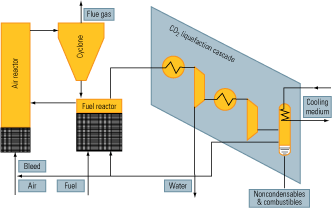
Chemical looping. Chemical looping makes it possible to perform both fuel combustion and CO2 separation in a single piece of equipment. It is a closed-circuit ion transfer process that uses a metal oxide to transfer oxygen from the combustion air to the fuel. As with ITMs, direct contact between fuel and combustion air is avoided.
The process (Figure 8) is made possible by two fluid reactors operating as an oxygen exchanger with interconnected fluidized beds. In the fuel reactor, the metal oxide is reduced by reaction with the fuel. Its outlet gas consists of CO2 and H2O. In the air reactor, the reduced metal oxide is oxidized by air. Its outlet gas consists of nitrogen and a reduced amount of oxygen. The net chemical reaction (pseudo-combustion) of the two reactors is the same as for normal combustion with the same amount of heat released. The advantage is that CO2 is inherently separated off, eliminating the need for auxiliary power.
|
8. Indirect combustion. The flow of a chemical looping system. Source: IMTE AG Consulting Engineers

|
CO2 hydration. CO2 hydrates are especially compatible with water-gas-shift reactors. The process relies on water’s ability to create hydrates in the presence of CO2 at high pressure and very low temperature. As Figure 9 shows, CO2 is hydrated in the formation reactor, which receives nucleated water from another reactor.
|
9. Remember to hydrate. The flow of a CO2 hydration process. Source: IMTE AG Consulting Engineers

|
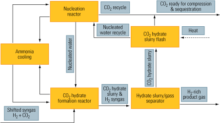
The nucleation process creates enough active nuclei centers in a solvent—in this case, water. Next, the nuclei promote massive hydration of CO2, creating the hydrate slurry. Finally, the CO2 is separated from its hydrate slurry. The upside of the process is that this separation can be accomplished efficiently, at low capital and operating costs. The downside of the process is that it requires ammonia cooling.
—Peter Luby and Miro R. Susta are principals of IMTE AG Consulting Engineers (www.imteag.com), a Swiss firm specializing in clean energy technologies. They can be reached at [email protected] and [email protected], respectively.