Digital Networks Prove Reliable, Reduce Costs
The debate over the benefits of using digital bus networks as the communications backbone of new power plants is all but settled. The technology is maturing, and the reliability of digital hardware is superior to that of hardwired systems. Newmont Gold Mining’s 200-MW TS Power Plant is perhaps the power industry’s best example of how a plantwide digital controls architecture can provide exceptional reliability and be significantly less costly to install.
Newmont Gold Mining’s 200-MW TS Power Plant (TSPP) (Figure 1) was a POWER 2008 Top Plant, and a complete description of the plant’s design features can be found in the October 2008 issue. However, that article only devoted a single paragraph to describe what we believe is the most advanced digital bus architecture ever installed on a coal-fired power plant. This article provides details of the TSPP control architecture, equipment selection, and many of the lessons we learned during this project. It also demonstrates the cost and potential schedule improvement opportunities of using advanced digital architectures in future plants.
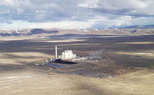
1. Out of sight. TSPP, located in Eureka Country, Nevada, gives new meaning to the words “remote I/O.” Courtesy: Fluor
Fluor Power was selected as the engineering, procurement, construction, and commissioning (EPCC) contractor to complete TSPP in July 2004. Newmont selected DTE Energy as the owner’s engineer to work with Fluor in developing the plant design specifications and for consultation in reviewing Fluor’s designs. DTE Energy was also contracted by Newmont to provide construction oversight services and began providing Newmont O&M services when the plant was commissioned in early 2008.
Digital Bus Networking Saves Time and Money
The traditional power plant distributed control system (DCS) architecture provides device control and monitoring via hardwired signals over a shielded twisted pair of wires and has been the standard in new plant design for decades. Electronic signals are sent to devices (transmitters, control valves, electric motor – operated valves, and the like) by varying the current through the circuit with a signal that ranges from 4-20 mA. This design requires each individual device signal wire to either "home run" back to the central plant DCS server room or a field-located DCS input/output (I/O) cabinet. A single plant may have thousands of these devices. Sometimes there are multiple signal and control cables from each device, with many devices even needing a separate power feed that further adds to the number of wires that must be individually installed.
Digital bus networking uses a similar means of signal transport over a shielded twisted pair of wires. In a digital burst, the signal is transmitted by varying the voltage on the two wires as opposed to an analog current signal, and multiple devices are allowed to share the same wires. This single cable is typically referred to as a "trunk" or "segment." The devices connected to the segments are called drops or spurs. Segment protectors are located along the trunk or segment as a point of connection for multiple instruments located on separate spurs. The segment protectors sustain the network should there be a loss of an instrument along the trunk line. The devices connected to the segments can communicate integrally, without requiring a DCS controller in between. In addition to transmitting signals, power to some devices is handled through the same shielded twisted pair of wires.
The major benefits of digital bus networks are the cable purchase savings and the follow-on material and labor savings associated with their installation, either in underground conduit or overhead tray (Figure 2). The potential savings can be significant: One control system supplier has suggested that life-cycle savings up to $20 million over conventional hardwired analog controls is possible on a greenfield 800-MW coal-fired power plant.
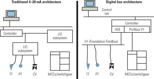
2. Old and new. This diagram compares a traditional analog architecture with the new digital bus architecture for power plant controls. Source: Fluor
Critical Design Decisions
Delays in receiving TSPP’s air permit restricted Newmont’s advanced material purchases to critical path equipment only, such as the steam turbine and boiler — not the plant DCS. Based on prior traditional power projects, there was no incentive to select the DCS supplier too early in the project because the I/O count and the plan for the distributed network was far from being finalized. The old assumption that early DCS supplier selection isn’t critical is not necessarily true with the new digital architecture — at least not until there is more widespread acceptance within the power industry, equipment supplier capabilities improve, and communications interface development mature.
Although many equipment and instrument suppliers say that they support communications on digital bus networks, even with the establishment of the Fieldbus Foundation, Profibus protocols, and DeviceNet standards, you must be very specific about the design approach used for the interface (down to software revision, master/slave definition, and the like). The earlier you select the DCS supplier, the sooner these requirements can be strictly specified in major and minor equipment specification requirements, thus reducing future supplier change requests. As more digital architecture power plants are constructed, supplier familiarity and support of advanced plant controls will certainly reduce lead times to those of the more conventional analog schemes.
The later purchase of the DCS, and therefore the bus interface, required a few exceptions to the goal of using a comprehensive digital bus architecture at TSPP. For example, the TSPP project team determined that the boiler burner management system would be hardwired in accordance with traditional DCS power plant architecture. Additionally, the steam turbine generator’s control system would be purchased with the turbine and would be hardwired; however, the control system would communicate to the plant DCS via a digital communications platform.
All other process controls and monitoring were eligible for consideration as part of the digital bus network. Evaluation was based on suitability of the data transferred with an available bus protocol, potential cable savings, and complexity of the interfaces required.
Many Competing Protocols
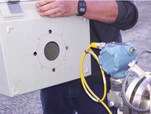
Multiple technologies are available for digital communication in the plant environment network, including Foundation Fieldbus, Profibus, and DeviceNet (Figure 3). Each has its own limitations, implementation requirements, and capabilities. Selection of the correct approach must be made by an experienced control systems engineer familiar with the scalability and robustness of each protocol.
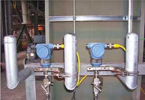
3. One-wire communications. Typical Foundation Fieldbus devices used at TSPP. Courtesy: Fluor
Consultation with DCS suppliers and major equipment suppliers is vital to ensure that an appropriate protocol selection is made and that optimum, reliable, and cost-effective performance is achieved. The final selection of the architecture should be made in collaboration with the DCS supplier to minimize interface issues down the road and ensure the bus interface requirements are well defined in all equipment purchase specification.
All equipment specifications must have a well-defined scope of work that includes a clear definition of the interface handoff at the purchase boundaries. For TSPP, definition of the interfaces was made; however, complications arose in some applications due to compatibility with varying revisions, master/slave drivers, and late supplier software changes.
We also made a conscious effort to standardize our device supplier and communications protocols where possible. Communications protocols should be defined in advance and be limited to certain particular protocols that are supported by the DCS supplier in order to minimize the use of protocol converters and commissioning interface issues that will inevitably appear later in the project.
If a certain supplier cannot support the defined communications protocols, then a traditional hardwired installation may be more practical than trying to implement an additional, new protocol. For example, at TSPP the design team recognized that there would be multiple applications where variable frequency drives (VFD) would be employed — some VFDs purchased direct by Fluor and some provided through subsuppliers of major equipment packages. Standardizing on a single supplier reduced the number of communication interface types and simplified factory acceptance testing.
Next, we made sure the project had a well-defined tagging convention as part of the system architecture design. Assignment of tags to devices needs to be established for automated devices, and the tag-naming convention needs to be compatible with the constraints imposed by the DCS system. For instance, the tag names on Fluor piping and instrumentation drawings drawings were consistent with regard to the number of subfields and the number of characters in the subfields of the tag name, but the electrical single lines with equipment with DCS interfaces did not include a loop number, which made it difficult to define the interface of these devices with the DCS.
One design approach we used at TSPP was to provide more than the typical number of spares in remote I/O cabinets. This extra space served as an insurance policy against some digital devices dropping back to a hardwired configuration should a digital communications approach not be feasible. As it turns out, the additional space was only needed in a couple of instances, but this preplanning saved much time and money later in the project.
Table 1 summarizes the various types of communication protocols used at TSPP by type. Table 2 illustrates the shift from the traditional control system structure "hard" I/O to the more advanced "soft" I/O system architecture in terms of their percentage use at TSPP.
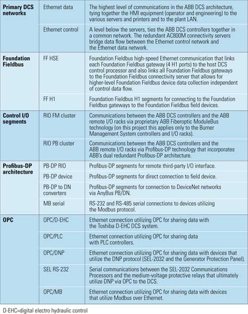
Table 1. Communication protocols used at TSPP. Source: Fluor
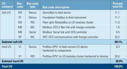
Table 2. Percentages of I/O bus architecture type at TSPP. Source: Fluor
DCS Selection Criteria
ABB’s 800xA series equipment was selected as the DCS for TSPP in August 2005. One of the key selection criteria was ABB’s open system design, which is well-suited for this project given the numerous types of communications employed at this plant.
The criteria for selecting a DCS supplier on a large-scale digital project must be heavily weighted on the experience the particular supplier will bring to the project. The value added in working with a supplier that has significant experience interfacing with a broad range of devices through various communication protocols was paramount to our success with this complicated digital bus network project.
Additionally, the field support structure the DCS supplier has in place, and the supplier’s experience in commissioning these systems, is very important in the evaluation. Given the multitude of communications protocols, the skill level of the supplier’s DCS technicians and engineers must be part of the evaluation criteria. In the past, many control system suppliers provided many "generalists" supporting the traditional analog DCS. Today, multiple highly qualified technicians familiar with the base control system platform language itself and the communications protocols may be necessary.
DCS supplier training, with a key emphasis on interfaces, should also be part of the DCS supplier evaluation.
Beyond the DCS
There are multiple approaches to designing and implementating the segment definition and device assignment. Finding the best approach for this digital bus project depended largely on the project schedule, availability of supplier information, definition of device locations, the number and skill of the field engineering staff, and complexity of the network. DCS supplier controller processing speed, loading, and critical loop definition can also be used to evaluate segment assignments.
Unfortunately, most new power projects don’t have the luxury of a completed design prior to the start of construction. The potential schedule gains and early project completion opportunity associated with fast-tracking projects typically outweighs the additional risk of field rework due to late supplier information and design completion. Newmont’s TSPP was no exception: Construction was mobilized when engineering was just over 50% complete.
Where final design information was unavailable, instrument location drawings were developed based on preliminary data or good engineering judgment given the processes and plant general arrangement. Instruments were located in the plant 3-D model and plan cuts made to produce construction drawings. The instruments directly purchased by Fluor (typically installed on Fluor-supplied pipe and equipment) were much easier to locate in the plant 3-D model than equipment supplier – provided instruments.
After development of these instrument location drawings, a "first-pass" Fieldbus segment assignment was made. The power draw for devices on the segment and the length of the segment will impact segment topology, and these factors were also considered in the design. Fieldbus wiring guidelines typically limit the number of devices on each Fieldbus segment to 32, but this number is derated to 16 devices if powered by the segment, and further reduced to just six devices if they are in intrinsically safe applications. The Fieldbus Foundation further recommends that spur lengths be limited to 120 meters (393 feet).
There is one downside of the digital bus architecture: If a single trunk cable fails, there are potentially more devices in jeopardy than if you lose a wire to a single 4-20 mA hardwired device (Figure 4). This is another consideration in segment assignments, as multiple "critical" instruments may be segregated to ensure that failure of any single segment does not cause a catastrophic failure or a plant forced outage.

4. Safe and secure. This segment protector installation at TSPP serves as the communications hub for multiple digital bus devices. Courtesy: Fluor
Factory Acceptance Testing
Unlike the traditional straightforward 4-20 mA interfacing between the control system and monitoring equipment and instruments, digital bus projects must deal with the communication interfaces necessary for an open control system design. Proponents have suggested that one of each like-kind of instruments or devices be sent to the DCS manufacturer’s shop for functional testing and to ensure that the communications interface is verified. For like-kind devices, we believe it is critical that the exact software and appropriate revision used for factory acceptance testing is the same as what will be deployed on the project. We believe this approach was well worth the additional coordination expense incurred.
Construction and Commissioning
One of the greatest benefits of digital bus architecture is the reduced need for expensive analog system cables. Fluor evaluated the cable savings potential at project initiation versus a similar-size reference plant that had traditional control system architecture with the majority of the I/O hardwired. Beyond the direct cable savings, benefits were realized in fewer cable trays, smaller cabling corridors/rooms, less physical congestion, and lower labor density in work areas. All of these benefits contributed to greater construction productivity. For TSPP, the projected cable savings was approximately 30% of the total cable footage.
In the event that an instrument is located too far from the assigned segment protector, construction can add an additional segment protector daisy-chained to take full advantage of the Foundation Fieldbus available trunk line length limits rather than change the way the instruments are assigned in the DCS (Figure 5).
5. Plan ahead. A typical level transmitter is shown with excess prefabricated cable coil. The excess cable is due to using precut lengths with shop-installed connectors to ease installation. Courtesy: Fluor
The typical commissioning process includes a point-to-point check or "loop check" of each control and signal wire from the control room DCS to the field device. Loop checks using traditional 4-20 mA hardwire communications serving as the primary means of data transfer always seem to eventually become the critical path tasks to complete construction and to begin the commissioning tasks.
The digital bus architecture used at TSPP streamlined much of the traditional loop checking, thereby significantly accelerating the wire-checking process. The traditional loop check metrics are often based on the number of loops completed per day in a given shift. Though the rate of loops completed per shift can be improved on a digital bus project with more field device technicians, control room density for the other end of the loop usually limits the number of checks possible at any particular time (Figure 6).

6. Digital domain. The control room operators oversee the network of device communications at Newmont’s TSPP. Courtesy: Fluor
Another advantage of the streamlining that the DCS enabled concerned labor. The remote, high-desert area around TSPP made it difficult to attract and retain experienced electricians. Any design planning or advanced technology that could help reduce the need for onsite labor was especially beneficial at TSPP given the plant’s remote location.
Future Digital Networks
Newmont’s TS Power Plant project provided Fluor the unique opportunity to broaden its experience using digital bus communications in the power industry. Since entering commercial operation in June 2008, TSPP has operated with an annual availability greater than 95% and an availability of 100% thus far for 2009 going into its first planned annual outage in May, demonstrating that the digital bus architecture is here to stay.
We have built on the lessons learned at TSPP and further broadened the use of digital communications on a more recent power project, a 2 x 800-MW supercritical coal-fired facility that is currently being constructed and commissioned. As with any new technology advancement, experiences gained will benefit future project executions and the way engineers approach implementation.
The authors wish to acknowledge the technical expertise and support of Patrick Wilhelm, an electrical design engineer at Fluor. His contributions to this article and to the successfully implementation of the digital bus network at TSPP are greatly appreciated.
—Ali Abdallah, PE is electrical and ocntrols supervisor and James H. Brown, PE, PMP ([email protected]) is director of design engineering—solid fueled projects for Fluor Corp.