DG interconnection standards remain elusive
This April, when the U.S. Department of Energy (DOE) released a report titled "The Potential Benefits of Distributed Generation and Rate Related Issues That May Impede Their Expansion," the agency noted that, "in some cases, [interconnection] rules and requirements are excessive, arbitrary, time-consuming, and add unnecessary costs to [distributed generation (DG)] projects." The report, prepared by the DOE in consultation with the Federal Energy Regulatory Commission (FERC) as mandated by the Energy Policy Act of 2005, identifies the potential benefits of cogeneration and small power production and the barriers that may prevent developers of DG projects from achieving them.
According to the report, interconnection of a DG plant to a utility’s grid remains shockingly problematic in many regions of the U.S. nearly 30 years after the passage of the Public Utility Regulatory Policies Act of 1978. Due to the lack of standards among utilities, many owners of small (10 MW or less) grid-connected DG plants are subjected to excessive costs and discriminatory practices that leave them with little recourse but to pay the bill when it comes. Some owners also complain about overly burdensome technical requirements that exceed those normally used to protect both a plant and the grid it supplies. The report also found that "there are no standard models, tools, or techniques for utilities to evaluate DG and incorporate DG resources into electric system planning and operations."
Pick your poison
Several model interconnection standards have been proposed, by:
- The U.S. Environmental Protection Agency’s Combined Heat and Power Partnership (www.epa.gov/chp/).
- The National Association of Regulatory Utility Commissioners. NARUC’s "Model Distributed Generation Interconnection Procedures and Agreement" was published in 2002.
- The Interstate Renewable Energy Council (2005).
- The National Rural Electric Cooperative Association (2006).
The most recognized and accepted standard is IEEE Standard 1547, titled "Standard for Interconnecting Distributed Resources with Electric Power Systems" (2003). Standard 1547 (the "Standard") leads the pack because it was vetted through the peer review process of the American National Standards Institute and includes a realistic framework of rules and requirements. Its stated goal is to serve as a single document of standard technical requirements for DG interconnection with which all plant owners and utilities must comply. Because adoption of any standard is the prerogative of individual states, acceptance of the Standard has been slow. California, with its Rule 21, and New York, which has set statewide specific technical standards, are notable exceptions.
All of the proposed standards listed above recognize that the major function of interconnection protection is to prevent system islanding by detecting asynchronous DG operation. In other words, it’s critically important to determine when the generator is no longer operating in parallel with the utility grid. The system protection design also:
- Disconnects the DG when it is no longer operating in parallel with the utility system.
- Protects the utility grid from damage caused by connection of the DG. Among the main causes of such damage are transient overvoltages and the fault current supplied by the DG, which can damage utility equipment and/or cause loss of relay coordination, resulting in unnecessary utility customer outages.
- Protects the DG from damage from the utility system, especially through automatic reclosing.
Although the focus of all of the standards is clear, a number of holes remain in the Standard that a robust interconnection design must address. DG developers should seriously consider the technical suggestions that follow. Be proactive and develop well-thought-out solutions that address these gaps in the Standard before approaching utility planners with an interconnection plan for your proposed project. To its credit, the IEEE is moving forward with a number of standards-making working groups to address the holes in IEEE 1547.
Protection: A two-way street
Most 10-MW or smaller distributed generators are connected to the local utility grid at the distribution and subtransmission level. These utility circuits are designed to supply radial loads. Distributed generators need to be protected not only from short circuits but also from abnormal operating conditions that the utility system can impose. Examples of such abnormal conditions are overexcitation, overvoltage and undervoltage, unbalanced currents, abnormal frequencies, and excessive torque on turbine rotors resulting from utility automatic reclosing.
If a generator is subjected to these conditions, it may be catastrophically damaged in a matter of seconds. This is obviously a major concern of DG owners. Utilities, on the other hand, are more concerned that the interconnection of DG will damage their equipment or that of their customers.
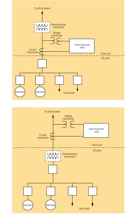
The Standard provides limited specific guidance on damage prevention other than calling for over/underfrequency and over/undervoltage interconnection protection. However, it does specify that the protection be installed at the Point of Common Coupling (PCC) between the DG and the utility system. The installation can be either at the secondary of the interconnection transformer (Figure 1, top) or at its primary (Figure 1, bottom), and the choice will determine who incurs the transformer losses. The circuit to protect the generator itself is typically installed at its terminals.

1. Take a side. Typical interconnection protection applied at the secondary (top) or primary (bottom) of the interconnection transformer. Source: Beckwith Electric Co., Inc.
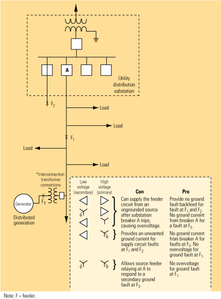
Most DG plants of 10 MW or less are connected to a utility’s distribution grid. In the U.S., most distribution systems are multigrounded four-wire designs whose voltage ranges from 4 kV to 34.5 kV. This design allows single-phase, pole-top transformers (which typically constitute the bulk of the feeder load) to be rated at line-to-neutral voltage. Thus, on a 13.8-kV system, single-phase transformers would be rated at 13.8 kV/1.73 = 8 kV. Line-to-neutral-rated transformers and lightning arrestors can be subjected to damaging overvoltages depending on the choice of DG interconnection transformer. Five different kinds of transformer connections are widely used to interconnect dispersed generators to the utility grid (Figure 2, bottom). Each has advantages and disadvantages, as noted.

2. Five easy pieces. Alternatives for connecting interconnection transformers. Source: Beckwith Electric Co., Inc.
The Standard cites obvious requirements for interconnecting DG but offers insufficient methods, solutions, or options for meeting them. The guidance is at such a basic level that not enough detail is provided to complete an interconnection design. Following are six major areas where the Standard definitely requires refinement.
Problem #1: Inadequate guidance on DG interconnection transformer grounding
With a single sentence, the Standard glosses over the complex issue of overvoltages caused by DG interconnection transformer grounding: "The grounding scheme of the DG interconnection shall not cause overvoltages that exceed the rating of the equipment connected to the area electric power system and shall not disrupt the coordination of the ground fault protection on the area electric system." The lack of implementation details makes this a major shortcoming of the Standard. The utility and owner have only two choices in selecting the primary winding configuration of the interconnection transformer.
Ungrounded primary transformer windings. The major concern with an interconnection transformer with an ungrounded primary winding is that when substation breaker A in Figure 2 trips in response to a permanent ground fault at location F1, the multigrounded system becomes ungrounded. This subjects the L-N (line-to-neutral) rated pole-top transformer and lightning arrestors on the unfaulted phases to an overvoltage that can approach L-L (line-to-line) voltage. This situation will arise if the distributed generator’s output is near the capacity of the load on the feeder when breaker A trips. The resulting overvoltages will saturate the pole-top transformer, which normally operates at the knee of the saturation curve.
Many utilities use ungrounded interconnection transformers only if a 200% or greater overload on DG occurs when breaker A trips. During ground faults, this overload level will not allow the voltage on the unfaulted phases to rise higher than the normal L-N voltage, avoiding pole-top transformer saturation. For this reason, ungrounded primary windings should usually be reserved for smaller DG, where overloads of at least 200% are expected on islanding.
Grounded primary transformer windings. This connection option has two major disadvantages: It provides an unwanted ground fault current for supply circuit faults, and it reduces the current from breaker A at the utility substation. This can produce a loss of relay coordination. Consider the following cases:
- If the fault is near the end of the feeder, the reduction in substation ground fault current may prevent the substation ground fault relay from responding to the fault. If that is the case, the utility will have to add pole-top line reclosers to detect ground faults near the end of the feeder circuit.
- If the utility uses a "fuse-saving scheme," the reduction of source current and the increase in current passing through the fuse can produce the same negative result: a loss of coordination with substation relaying.
- If the fault is on an adjacent feeder (F2 in Figure 2) the resulting ground current flow through the substation bus could result in a loss of coordination and the undesirable tripping of breaker A. To avoid this situation, the overcurrent feeder relays at breaker A may have to be made directional, so they respond only to faults on feeder A.
Wye-grounded (primary)/delta (secondary) interconnection transformer connections. With this connection it’s important to note that even when DG is off-line (the generator breaker is open), ground fault current will still be provided to the utility grid if the interconnection transformer remains connected. This would be the usual case because interconnect protection typically trips the generator breaker. The transformer at the dispersed generator site acts as a grounding transformer with zero sequence current circulating in the delta secondary windings. In addition to these problems, the unbalanced load current on the system—which, prior to the addition of the interconnection transformer, had been returned to ground through the main substation transformer neutral—now splits between the substation and the DG transformer neutrals. This can reduce the load-carrying capabilities of the DG transformer and create problems when the feeder current becomes unbalanced due to operation of single-phase protection devices such as fuses and line reclosers. Although wye-grounded/delta transformers are universally used to connect large generators to utility transmission grids, they pose major problems when used on four-wire distribution systems.
Wye-grounded (primary)/wye-grounded (secondary) interconnect transformer connections. The major concern with using an interconnection transformer with grounded primary and secondary windings is that it also provides a source of unwanted ground current for utility feeder faults, similar to that described in the previous section. It also allows sensitively set ground feeder relays at the substation to respond to ground faults on the secondary of the DG transformer (F3 in Figure 2). This can require the utility to increase feeder ground relay pickup and/or delay tripping to provide coordination. The reduced sensitivity and speed of response to feeder faults can put feeder circuits at risk of damage.
Problem #2: DG ferroresonance not addressed
The phenomenon of self-excitation of induction generators has been known for many years. It occurs when an isolated generator is connected to a system with a capacitance that is equal to, or greater than, the magnetizing reactance requirements. Depending on the value of the capacitance and the power loading on the machine, voltages in the island of 1.5 to 2.0 per unit can be produced.
Compounding the problem of islanding DG with distribution system pole-top capacitor banks, a unique form of ferroresonance may occur that is not confined to induction generators but also can occur on synchronous machines. Overvoltages of over 3.0 per unit may be produced. Discharging and charging of the system capacitance through nonlinear magnetizing reactance of the DG interconnection transformer produces the overvoltages.
The ferroresonance associated with DG differs from the traditional ferroresonance caused by single-phase switching in that no unbalanced condition is necessary. If all of the following conditions exist, ferroresonance can occur:
- The DG must be separated from the utility source (islanding condition).
- The load in the island must be less than three times the rating of the DG.
- The system capacitance must be greater than 25% and less than 500% of the rating of the DG.
- There must be a transformer in the circuit to provide nonlinearity.
How can such overvoltages be mitigated? Studies have shown that both induction and synchronous generators and all types of interconnection transformer connections are susceptible. Surge arresters will clip the peaks of the overvoltage, but they will not suppress the ferroresonance condition and they may be damaged in the process. Metal-oxide arresters may survive longer but also can be damaged. The most practical solution is to trip the DG to remove the driving source. This is not as simple as it sounds, because the voltage wave shape for this resonance condition is nonsinusoidal, and most digital relays used today for interconnection protection operate on RMS 60-Hz sinusoidal overvoltage, One relay manufacture has address this problem though an instantaneous overvoltage relay (59I relay) that responds to peak overvoltage.
Problem #3: Inadequate discussion of interconnection protection options
The functional levels of interconnection protection vary widely and depend on factors such as the generator size, the point of interconnection to the utility grid (distribution or subtransmission), the type of generator (induction, synchronous, or asynchronous), and the configuration of the interconnection transformer. The functional requirements of relays can be specified to meet the specific objectives of an interconnection protection system. Other than a very simplistic discussion of the detection of loss of parallel operation with the utility grid, the Standard does not address protection areas such as fault backfeed removal, abnormal power flow, damaging system conditions, or restoration practices.
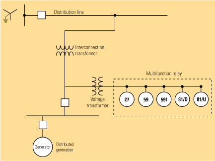
The most basic and universal way to detect the loss of parallel operation with the utility grid is to establish an over/underfrequency (81 O/U relay) and over/undervoltage (27/59 relays) "window" within which DG is allowed to operate. When DG is islanded from the utility system, either due to a fault or other abnormal condition, the frequency and voltage will quickly move outside the operating window if there is a significant difference between load and DG output level.
If the load and generator are near balance at the time of separation, voltage and frequency may stay within the normal operating window and under/overfrequency and over/undervoltage tripping may not take place. If this is a possibility, it may be necessary to use transfer trip and a reliable means of communication.
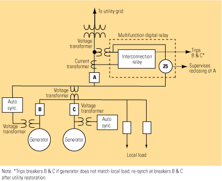
When the loss of parallel operation is detected, the distributed generator must be separated from the utility grid quickly enough to allow the utility breaker at the substation to automatically reclose. High-speed reclosing on the utility system can occur as quickly as 15 to 20 cycles after the utility substation breaker trips. The utility must provide guidance to the DG owner about the speed of separation required. It may be necessary to add source voltage supervision and synchrocheck reclosing to the substation reclosing scheme if underfrequency trip times are extended. Figure 3 illustrates such a modification, which prevents reclosing of the substation breaker prior to disconnection of the dispersed generator. Figure 4 shows a typical basic over/undervoltage and over/underfrequency scheme for a small DG installation. Basic protection functions can be implemented by a single multifunction digital relay.

3. Simple mod. Adding source voltage supervision and synchrocheck reclosing to the substation reclosing scheme prevents reclosing of the substation breaker prior to disconnection of the DG plant. Source: Beckwith Electric Co., Inc.

4. Solid solution. A circuit for protecting a small distributed generator that uses a solid-state multifunction relay. Source: Beckwith Electric Co., Inc.
The use of underfrequency relays, coupled with the need to separate the DG prior to utility breaker reclosing, precludes the ability of most DGs to provide power system support to the utility during major system disturbances. When frequency decreases due to a major system disturbance, these generators will trip off-line. It may be possible to reduce underfrequency settings to comply with regional independent system operator requirements, but the required trip time usually cannot be extended to exceed automatic reclosing times. The need for distributed generators to provide some system support will become more critical if DG’s share of total generation increases over the next 10 years, as some forecasts predict.
One way to mitigate this problem is to use rate-of-change frequency (81R relay) protection. This technique is widely used outside the U.S. in lieu of, or in conjunction with, underfrequency (81 relay) relaying to detect islanding of DG. It offers the advantage of more rapid tripping for severe DG overloads while allowing DG to remain connected to the system when frequency is being slowly dragged down due to the loss of utility generation.
California’s Rule 21 requires the use of a directional power relay (32 relay) to detect the loss of parallel operation with the utility grid. The provision only applies to DG units that are installed for peak shaving or load following and that do not sell power back to the utility. The scheme is applied where minimum verifiable local load is 50% or less of the distributed generator’s total installed capacity. Typically, at the DG facility a 32 relay is set to operate when power flow into the generator bus is below 5% of the facility’s DG total capacity. Figure 5 illustrates this scheme. Standard 1547 does not discuss this option for detection of loss of parallel operation with the utility.

5. West Coast rules. California Rule 21 specifies the use of directional power relaying to detect the loss of synchronous operation with the utility grid. The provision applies only to DG units that are used for peak shaving or load following and do not sell power back to the utility. Source: Beckwith Electric Co., Inc.
Problem #4: Insufficient discussion of using DG fault current for interconnection protection
Induction generators provide only two or three cycles of fault current to external faults. Small synchronous machines are typically so overloaded after the utility substation breaker trips that their fault current contribution is very small. These generators do not need specific fault backfeed detection. For these small generators, the use of 81O/U and 27/59 relays to detect the loss of parallel operation is all the interconnection protection necessary.
The larger the synchronous DG source, the greater the chance of its contributing significant current to a utility system fault. Typically, a 67-, 21-, or 51-V relay can be used to detect supply fault and initiate DG separation.
The choice of a device for removing ground fault backfeed should be a function of the type of primary winding on the interconnection transformer. For a grounded primary transformer winding, a 51N neutral overcurrent relay or, in some cases, a 67N ground direction relay should be selected. For ungrounded interconnection transformers, neutral overvoltage relays (59N, 27N relays) provide detection of supply ground faults.
The voltage transformers (VTs) that supply these relays (59N and 27N) should have their primary windings connected line-to-ground. These primary VT windings are usually rated for full line-to-line voltage. Many utilities use a single VT with 59N and 27N relays, or three VTs connected in a broken-delta configuration. Figure 6 shows a typical protection scheme used on a DG with an ungrounded interconnection transformer.

6. Four in one. A multifunction relay can prevent four problems common to moderately sized DG plants attached to utility grids via an ungrounded (primary) connection. Source: Beckwith Electric Co., Inc.
Problem #5. Poor detection of damaging conditions
Unbalanced current conditions caused by open conductors or phase reversals on the utility supply circuit can subject a DG plant to a high-amplitude negative sequence currents. The operation of single-phase protection devices (such as fuses and line reclosers) on the utility distribution grid can produce the same result. High negative sequence currents can cause a generator rotor to heat up quickly, causing considerable damage.
Many utilities use a negative sequence overcurrent (46 relay) to provide protection against unbalanced currents as part of their interconnection package. A few use a negative sequence voltage relay (47 relay) to guard against phase reversals caused by inadvertent "phase swapping" after power restoration.
Another damaging condition that can affect synchronous generators—particularly reciprocating engine prime movers—is loss of synchronism, produced by prolonged exposure to a slow-clearing utility system fault. Reciprocating engines are especially vulnerable because they have little inertia. An out-of-synchronism condition can produce shaft torque damage.
Reciprocating engines are driven out of synchronism by a sudden imbalance of their generator’s electrical and mechanical power output. Electricity power output can suddenly be curtailed by a severe, slow-clearing (generally three-phase) short circuit, while mechanical power output during the fault remains unchanged. A large imbalance between electrical and mechanical output can cause a generator to accelerate rapidly, causing the loss of synchronism.
To illustrate this point, consider the case of a utility system fault on the line side of a pole-top line recloser. Generally, line recloser tripping is delayed to coordinate with down-line fuses. Tripping of the substation breaker also is delayed to coordinate with the line recloser. As a result, the distributed generator experiences a voltage dip although it hasn’t been disconnected from the grid. Because the system frequency at the DG remains at 60 Hz, the underfrequency relay will not trip. The undervoltage relay will certainly detect the problem, but it may not trip rapidly enough to prevent the loss of synchronism. A dedicated loss of synchronism protection (78 relay) may have to be installed to protect the generator from possible damage. Such protection also is available from multifunction digital interconnection relays.
The draft of IEEE 1547 included a substantial section on this topic, but it was removed during the balloting processes. California Rule 21 recommends applying loss of synchronism protection to synchronous generators large enough to contribute 10% of the total current to faults on the high-voltage side of the interconnection transformer. This requirement in California was also removed from Rule 21. Loss of synchronism and shaft torque damage are in fact a concern for engineers charged with designing interconnections for reciprocating engine–based DG facilities.
Problem #6: Insufficient restoration specs
After DG has been separated from a utility grid by an interconnection protection circuit, the link must be restored. Two DG tripping/restoration practices are widely used within the industry. The first restoration method is typically used where the DG’s capacity does not match the local load. In such cases, interconnection protection typically trips the DG breakers (Figure 7). To restore the connection, the DG breakers are typically resynchronized automatically.

7. Back on-line. Restoring the connection of a DG plant to a grid following a trip requires breakers to be closed in a specific order. Source: Beckwith Electric Co., Inc.
Many utilities require the installation of a synchrocheck relay (25) at the main incoming breaker to supervise reclosing to prevent unsynchronized closures. The synchrocheck relay is typically equipped with dead-bus undervoltage logic to allow its reclosure from the utility grid following a dead-bus condition at the DG facility.
The second restoration method is used where the DG and local loads match. In these cases, the interconnection protection trips the main incoming breaker. Many DG plants at petrochemical and pulp and paper factories use internal underfrequency load-shedding relays to match local load to available DG capacity after the connection is broken. Resynchronizing the DG plant to the utility grid requires a more-sophisticated synchrocheck relay that can measure not only phase angle but also the slip frequency and voltage difference between the utility and DG systems. Typically, such relays supervise automatic, manual, and supervisory reclosing.
—Charles J. Mozina is a contract consultant to Beckwith Electric Co., Inc. (www.beckwithelectric.com) specializing in electrical protection systems. He can be reached at [email protected].