Desuperheating valves take the heat
The cascading bypass system is perhaps the most common design for managing high-pressure steam in a combined-cycle plant. It is the hot reheat (HRH) bypass valve actuator that defines the valve’s ability to respond to system demands. That makes it perhaps the most important component in the steam bypass system, which in turn is one of the most important control loops in a typical combined-cycle plant.
HRH valves play a critical role in the main and reheat steam loops, especially during unit start-ups and shutdowns. If your control loops can’t closely follow a setpoint, chances are your plant is equipped with pneumatic actuators—and its heat rate is higher than it could be. Anything short of perfect control can also cause major operational problems that either extend start-up and shutdown times or increase the potential for unit trips. Both effects inevitably show up on the plant’s bottom line.
In cascading bypass systems, steam from the high-pressure (HP) and intermediate-pressure (IP) drums that bypasses the steam turbine during start-ups, transients, and shutdowns does not go straight to the condenser (Figure 1). Instead, HP bypassed steam goes to the cold reheat (CRH) line on the HP turbine’s exhaust and mixes with the output of the IP drum. This HP steam is then sent through the reheater and through another bypass pressure-control valve—the HRH valve—before going to the condenser.
1. Detours. A cascading bypass system uses an HP steam bypass valve and a hot reheat steam bypass valve to manage steam flow to the steam turbine. Source: Koso America Inc.
Selecting the right valve
HRH valve requirements are complex from a mechanical design standpoint. The ANSI 600-lb-rated valves range from 12 to 24 inches in diameter. They must tightly shut off and be able to be throttled (conflicting requirements for such difficult service), and their body and trim materials must deal with rapid thermal transients. Noise control and extended trim life also have become very important design requirements.
Unbalanced HRH valves are typically not used in this application because the actuation forces required for valves of this size would be too large for conventional pneumatic actuators. However, because tight shutoff is a design requirement, pilot-balanced trim is common. This design allows for the use of relatively low actuator thrust at full differential pressure (balanced when open), while enabling full unbalanced forces on the valve seat in the closed position (installed in the flow-to-close direction) to ensure tight shutoff.
Special materials, tolerances, body/trim/bonnet arrangements, and flow paths (warming lines, for example) are used to address the thermal cycling issues that HRH valves must deal with, such as weld fatigue and internal reliability. Many designs have forsaken pneumatic actuators fitted with standard positioners and volume boosters to meet stroking speed requirements in favor of smart positioners with boosters that improve diagnostic capabilities and reduce overshoot.
What would be a good set of technical requirements for a HRH valve actuator? The use of pneumatic actuators poses inherent design challenges because air is compressible and therefore limits the response, positioning capability, and stability of an actuator. Nevertheless, it’s still instructive to compare how a typical pneumatic actuator and a modern hydraulic actuator work. As long as you remember to include the effects of your plant’s design in the comparison, the following discussion will point you in the right direction.
Let’s begin the comparison by considering the following as typical HRH bypass actuator performance requirements:
- A stroke length between 6 and 12 inches.
- A stroking force between 15,000 and 40,000 pounds, depending on the valve design and the process parameters.
- A stroke speed typically less than 5 seconds between the full-open and full-closed positions.
- The ability of an input trip signal to stroke the valve fully closed within 2 seconds or less.
- High frequency response, repeatability, accurate setpoint control, and stability.
Pumping air actuators
Because pneumatic actuators can provide fast stroking speeds, they can usually be used reliably to handle steam turbine load shedding and trips. They also can catch condenser vacuum during large setpoint changes. However, the frequency response, repeatability, and dynamic stability of pneumatic devices are inherently limited due to the soft, compressible nature of their motive force—air. Static friction (“stiction”) is a key contributor to these performance limitations.
Graphite packing and seal rings are required for these high-temperature applications, and they add stiction to the actuator. Consider an 18-inch-diameter spring-opposed cylinder with a 7.5-inch stroke and a 120-psig operating pressure (Figure 2). For the piston to move upward, the positioner must vent air from the cylinder until its internal pressure has decreased enough to overcome the stiction. For this example, assuming that the force differential between static and dynamic friction is 2,200 lb (corresponding to an actuator pressure change from 120 psig to 111 psig), we can calculate that:

2. Force multiplier. A pneumatic actuator must vent compressed air, which compromises its performance. Source: Koso America Inc.
- The volume of air vented is 88.3 in3.
- The time required to vent this volume at 80F is 1.74 seconds, which represents the inherent lag of the actuator.
- The piston’s “jump” (the actuator’s resolution) is 0.35 inches, or 4.6% of its span.
Such an actuator would easily cause friction hunt (due to jump) and process limit cycling (due to lag). Friction hunts, stiction, and limit cycling (process instability) are all well-documented phenomena. They are among the biggest contributors to poor control loop performance and destabilization of process equipment.
Since a pneumatic positioner’s flow capacity (CvFL) will not allow fast enough stroking speeds for the application, volume boosters must be added. Doing so changes the lag in response as well as the overshoot jump values. Assuming a typical volume booster with a CvFL of 3.7 and a 200-ms response time, the dead time is reduced to 0.29 seconds and the jump becomes 1.09 inches, or 14.5% of span.
This lag in response and increase in jump is typical of pneumatic actuators. The volume boosters and positioner can be set up to reduce the use of the former for small setpoint changes. However, tight control on large setpoint changes is difficult to achieve.
Interpret the results
How tightly does the HRH bypass actuator need to control reheat pressure, given these typical design values? Clearly, overshoot of this magnitude is not acceptable for any pressure-control loop.
One option is to use a “smart” pneumatic positioner. It can significantly reduce overshoot, using complex control algorithms for overcoming the inherent limitations of pneumatic actuators discussed earlier. Although overshoot can be reduced, the magnitude of the reduction depends on the level of stiction in the valve, which is typically very high for large valves with graphite packing.
The downside of switching from standard to smart pneumatic actuators is that the latter take much longer to respond to control signal step changes of 2% or less. This dead time becomes longer as the step changes become smaller (a 1% change produces a longer dead time than a 2% change).
Along with dead time, an additional delay before reaching the setpoint is introduced by the proportional-integral-derivative (PID) action of the smart positioner, which must slow down in a controlled manner to minimize overshoot. This ramp into setpoint is slow compared to that of other actuator technologies. We can’t change the laws of physics.
Control loop stability is especially sensitive to dead time, which is perhaps the most destabilizing of the time-dependent dynamics of a control loop. Equally destabilizing is the tendency of the dead time to vary. Pneumatic actuators tend to exhibit dead time while the positioner transfers sufficient power air to the actuator to overcome friction and to move the valve closure member. Often, this tendency also is amplitude-dependent; as mentioned earlier, small step changes produce longer dead times than larger changes.
The main cause of this destabilization, called limit cycling, is controller “windup.” The lag in response to a step change in a control signal will cause the controller’s output (the actuator’s input signal) to continue to drift in the direction of the desired process variable change (because no change is seen during the lag). Once the fast-acting pneumatic actuator responds following the dead time, the valve will quickly overshoot the setpoint. After the controller sends out a corrective signal in the other direction and the dead time causes overshoot, the result is controller “hunting.”
Impact on the plant
Across some of a plant’s load range, oscillations caused by stiction, overshoot, and/or dead time may not cause any operational upsets. However, the oscillations will make associated spray valves and the feedwater valve more active if pressure and temperature are not stabilized by the HRH bypass actuator.
Steam turbine control. Even subtle changes in temperature or pressure add thermal/mechanical fatigue cycles. Poor control of reheat pressure can cause significant fluctuations in IP drum levels. Those swings can lead to gas turbine (GT) trips, safety valve trips, and variations in steam flow to intercept control valves (ICVs) or nozzle valves, depending on the turbine design. The ICVs, which regulate the steam input to the turbine, accelerate the unit, control its speed, and synchronize and apply its load.
Before admitting steam to the turbine through the ICVs, the HRH bypass actuator is responsible for balancing steam generation by stabilizing drum pressure and steam flow. The repeatability and stability of the actuator directly determine how quickly both parameters stabilize. Once temperature and pressure have stabilized, the hold period (used to allow the metal temperature of the HRSG drum to reach equilibrium) can begin; at its conclusion, the GT can be ramped to full load. The HP bypass actuator also plays a big role in this stabilization.
Starting a second unit. The HRH bypass actuator is responsible for matching the temperature and pressure of heat-recovery steam generators (HRSGs) and the steam turbine when a second unit is started in a typical 2 x 1 combined-cycle configuration. In this scenario, the time that it takes to “blend” one GT/HRSG into the on-line GT/HRSG and steam turbine depends directly on the control capability and stability of the HRH bypass actuator.
Blending and load control of combined-cycle plants have become increasingly important because the emissions of many plants now are regulated during their start-up as well. Combustion turbines operated at low loads are very inefficient and therefore produce excess NOx and CO during start-up. Delayed start-ups produce more emissions, not to mention lost generation sales. Until their temperature and pressure are under control, stable, and matched, neither the gas turbine nor the steam turbine can be ramped up to full load.
Condenser vacuum losses. Once a plant has been ramped up to 95% load, the HRH bypass actuators are completely closed and no condenser vacuum is lost through the HRH valves (as long as they remain tightly seated). But initial vacuum can be lost during start-up and when starting a second unit, unless the vacuum is maintained by the HRH bypass actuator. To keep condenser vacuum at the optimum level, the actuator must respond rapidly enough to steam flow transients to control the bypass to the condenser in a way that bypasses as little excess steam as possible. Also, if the HRH bypass valve is not stable, then more steam than necessary will go to the condenser, allowing its vacuum to decay.
Steam turbine operation. A cascading bypass system can increase the potential for “windage” overheating of the HP turbine during start-up and shutdown if the HP bypass and HRH bypass valves fail to precisely control HP and HRH pressure.
The reheater pressure must be tightly controlled at a low value, particularly during low-flow conditions (such as during start-ups), to keep the HP turbine’s back-end temperature below 800F. One way to control HP turbine exhaust temperatures is to install a start-up bypass system between the HP turbine exhaust and the condenser. This expense can possibly be avoided if the HRH bypass actuator can control reheat pressure precisely enough.
Hydraulic vs. pneumatic actuators
The scenarios outlined above represent real problems that combined-cycle power plant owners and operators are experiencing today. They will become even more common as more plants are forced into daily cycling service for which they were not designed.
Selecting hydraulic actuators instead of pneumatic actuators for critical desuperheating valve applications is one way to address cycling-related problems. Since oil is incompressible, performing the same response calculations as before, but this time for a hydraulic actuator, yields much better results: a dead time of just 0.00164 seconds and piston jumps in increments of just 0.00423, or 0.0564% of span.
Switching from pneumatic to hydraulic actuators virtually eliminates the lag in response to a control signal change and reduces jump to an insignificant level. Hydraulic actuation systems can be tuned for very fine setpoint control (down to 0.1% of span). In general, they feature very fast stroking speeds, 100% duty modulating service, unparalleled frequency response (millisecond dead times), immunity to dynamic instability and friction, and almost immeasurable overshoot.
But there are downsides to going with hydraulic actuators. Conventional hydraulic actuators have a reputation for being maintenance and reliability nightmares, and they cost much more than their pneumatic cousins. What’s more, hydraulic systems require motors to run 24 hours a day, as well as an extensive network of very high pressure hydraulic tubing and fittings that may leak. Plant owners and builders tend to avoid hydraulic systems for those reasons, preferring instead to specify advanced pneumatic positioner technology, regardless of its performance limitations.
To get an idea of the benefits of retrofitting, take a close look at Figure 3 (p. 55), which compares the performance of a typical hydraulic actuator to that of a pneumatic actuator with a smart positioner tuned for maximum response (shortest dead time). The test whose results are shown was performed with actuators tuned for identical stroking speed on valves with polytetrafluoroethylene (PTFE) packing. A pneumatic actuator can be adjusted for less overshoot, but doing so increases its dead time and makes its slowdown to setpoint begin earlier.
3. Out of sync. A hydraulic actuator like the Electraulic can be tuned for almost instantaneous response. A typical pneumatic actuator has an inherently longer dead time and responds more slowly to a setpoint change. Source: Koso America Inc.
Another possible way to avoid cycling-related problems is to select a digitally controlled hydraulic actuator optimized for low fluid usage. The Electraulic actuator (www.rexa.com) is a good example of this type of device (Figures 4 through 7). It uses 20 times less fluid (standard motor oil) than a typical central system; it has no separate pumping systems, reservoir tanks, or high-pressure hoses; no fluid maintenance or filtration is required; and its motor(s) only operate when a position change is required. Sounds almost too good to be true.
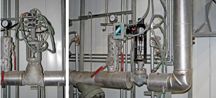
4. IP attemperator retrofit. Retrofit of a conventional hydraulic system actuator (top) to an Electraulic actuator (bottom) on the IP attemperator of a typical combined-cycle plant. Courtesy: Koso America Inc.
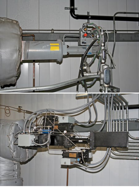
5. IP bypass retrofit. Retrofit of a conventional hydraulic system actuator (top) to an Electraulic actuator (bottom) in the IP bypass line. Courtesy: Koso America Inc.
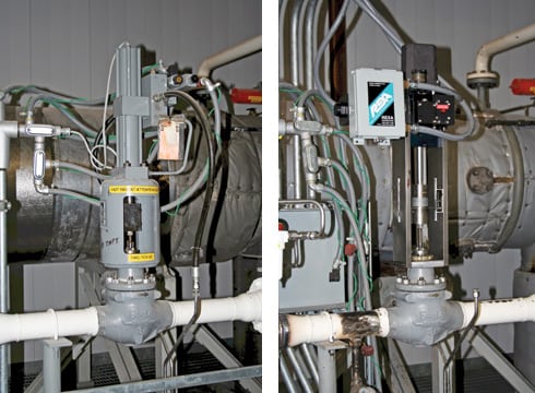
6. HP attemperator retrofit. Retrofit of a conventional hydraulic system actuator (left) to an Electraulic actuator (right) on the HP attemperator of a typical combined-cycle plant. Courtesy: Koso America Inc.
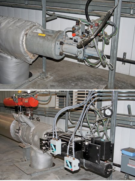
7. HP bypass retrofit. Retrofit of a conventional hydraulic system actuator (top) to an Electraulic actuator (bottom) in the HP bypass line. Courtesy: Koso America Inc.
Taking it to the bank
By retrofitting its pneumatic actuators to hydraulics one combined-cycle plant reduced its start-up times dramatically. It also reduced the time needed to blend a second GT/HRSG train into an on-line train from 2 hours to 50 minutes.
The plant decided to retrofit its pneumatic actuators after routinely experiencing hunting oscillations in the 35% to 55% stroke range. The oscillations created enough instability in reheat pressure to make it overshoot by 25 psi. Many efforts to tune the actuator and system (including the installation of a smart digital positioner) yielded no improvement.
Finally, the owner bit the bullet and replaced the pneumatic valve actuation system with a hydraulic system. The retrofit did more than eliminate the oscillations and instability; it also lowered the cost of starting up a second GT/HRSG train. The following bullet points detail the monetary savings and gains the plant continues to realize:
- Running the gas turbine at no load or low load for one fewer hour per restart saves $4,500 in natural gas priced at $10/mmBtu. The plant cycles one GT/HRSG train each night and brings it back on-line the next day during certain months. With 60 restarts every year, the plant conservatively estimates the annual value of this benefit at $270,000 in fuel savings.
- The faster the plant can restart in response to grid demand, the faster it can produce revenue. For example, one more hour of generation by the plant’s 170-MW GT (at full load), and one more hour of generation by its steam turbine at 80 MW (full load is 160 MW) at 5 cents/kWh adds up to $750,000 a year in increased revenue from power sales.
- Shorter start-ups allow for more of them each year, because the plant has an annual start-up emissions cap.
—Geoffrey Hynes ([email protected]) is international sales manager for Koso America Inc.