Defeating Concrete Reinforcing Steel Corrosion
Four concrete cooling towers at a coal-fired electrical generation plant exhibited reinforcing steel corrosion that was causing concrete deterioration. This case study follows the repairs to those towers—how the corrosion control solution was selected, how repairs were made, and how follow-up tests found the repairs to be effective three years later.
As early as the 1960s, corrosion of reinforcing steel in structural concrete was recognized as a threat to concrete structure durability. Steel embedded in newly cast concrete is protected by the high pH of the concrete. However, the passive film on the surface of the reinforcing steel is broken down over time by the infiltration of ionic materials, typically salts. Carbonation of the concrete, caused by diffusion of atmospheric carbon dioxide, can also break down the reinforcing steel passivation, allowing the initiation of corrosion.
Many variables affect the time it takes for corrosion to begin, including the concrete cover depth, temperature, concrete moisture content, pH level of the concrete, the presence of oxygen, and others. When corrosion begins, one region of reinforcing will become anodic and other regions will act as a cathode. The ensuing chemical reactions cause oxidation of the metal at the anode.
The oxidation product occupies a larger volume than passivated steel. As the bar oxidizes, an expansive tensile force is applied to the cover concrete, creating cracks and ultimately a concrete spall (flaking or crumbling). At this point, typically, the facility’s owner becomes concerned about long-term durability, and repair project planning is launched.
Repair Project Planning
During June 2000, the engineering team of a 1,660-MW coal-fired electrical generation station located in the southwest U.S. began planning a concrete repair project. The team had been observing concrete spalling and corrosion of reinforcing steel on specific reinforced concrete assemblies integral to the plant’s four concrete mechanical draft cooling towers. Two towers served Unit 1 and two served Unit 2.
The cooling towers are constructed primarily of precast concrete elements, with some conventionally reinforced elements. In the plan, the cooling tower is a 12-sided shape with an approximate 212-foot diameter.
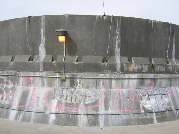
Each tower has 12 motorized fans designed to draft air from the lower level up through the tower. The moving air is heat exchanged with hot process water, ejecting steam out the top of concrete fan stack assemblies (Figure 1). The fan stack assemblies are constructed of a lower conventionally reinforced concrete ring measuring 41 feet 2 inches in diameter by 4 feet tall. The upper assembly is constructed of precast concrete panels bolted to the lower assembly. Corrosion of the reinforcing steel in the lower assembly was causing concrete spalling. The plant engineering team wanted to understand the source of deterioration and institute a repair plan for the problem.
 |
| 1. Four of a kind. The configuration of one of four cooling towers repaired as part of the project. Courtesy: Restruction Corp. |
Investigation Program and Results
Investigation of the corrosion source consisted of the following tasks:
- Visual assessment of all 48 lower fan stack assemblies and field measurement of concrete cover.
- Review of original structural drawings and details for the lower fan stack assembly.
- Chloride content analysis at depths of 1, 4, and 7 inches through the depth of the lower assembly concrete at six separate locations. A total of 18 chloride samples were tested.
- Delamination mapping of the assemblies.
- Petrographic analysis of two cores removed from different fan stack assemblies.
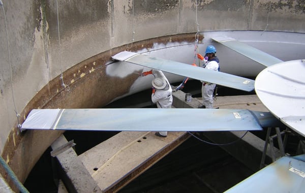
Visual assessment of the lower assemblies determined several items of concern, including the high-temperature environment, minimum concrete cover of ¾ inch, and water seeping down the outer face of the assembly at the joint between the upper precast and lower cast-in-place concrete. Constant contact with steam was causing elevated concrete temperatures and high moisture content. Each of these variables was contributing to the rebar corrosion (Figure 2).
 |
| 2. Much spalling found. The upper and lower fan stack assembly and the areas requiring repair on one of the four towers is shown. Courtesy: Restruction Corp. |
Review of the original structural drawings detailed the location, size, and placement of cement grout in the joint between the upper precast and lower cast-in-place concrete. Reinforcing details for the lower assemblies showed designed cover for reinforcing was 1 inch. Number 4 bars were spaced at 12 inches as stirrups over #4 hoop bars around the lower assembly circumference.
Chloride content samples were chosen to determine levels of water-soluble chlorides at the level of reinforcing and to determine if a chloride gradient existed in the concrete. The measurements were also used to determine if chlorides were cast into the mix. Average chloride content at 1 inch was 0.0581% by weight. Maximum chloride content in any sample was 0.144% by weight. ACI 318 (the American Concrete Institute’s Building Code Requirements for Structural Concrete) allows for a 0.15% chloride content in reinforced concrete exposed to chlorides in service for new construction. Generally, in the U.S., 0.30% chloride content is considered the threshold limit for initiation of corrosion. All chloride measurements fell below this limit.
Delamination mapping of the lower assembly concrete determined that, on average, 15% of the 600 square feet for each assembly was delaminated.
Petrographic analysis of the cores revealed poor air entrainment and locally abundant micro-cracks throughout the core body. The concrete was generally of good quality. Carbonation depth was measured at 0.13 inches.
Based on this information, conclusions were drawn regarding the source of corrosion. The effect of high concrete temperatures, high moisture content, and the wetting and drying action at the outside face of the assembly concrete were cause of the corrosion found on the cooling towers.
Repair Program
It became apparent that reducing the moisture content level within the concrete was the primary defense against future corrosion. Cutting off the moisture ingress would increase the concrete resistance, lowering the reinforcing steel corrosion rate. Reducing the concrete temperature was not a realistic expectation.
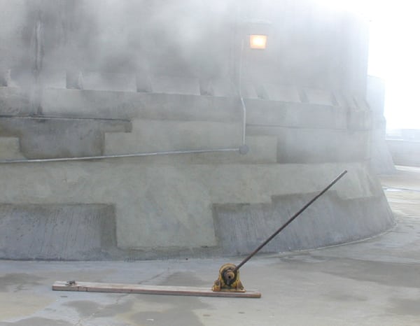
A coating system designed to lower concrete permeability was selected. The coating system selected started with a 100% solids moisture-tolerant epoxy primer applied at the rate of 100 square feet per gallon. The body of the coating was a 100% solids polyamide based, flake-filled epoxy (Figure 3).
 |
| 3. Coating tower interior. Coatings were applied in the lower assembly interior after repairs were completed. Courtesy: Restruction Corp. |
Access, surface preparation using 20,000-psi water lances, and coating installation would be accomplished during a 30-day plant shutdown.
Access was built using prefabricated wood joist and planks bearing on steel angle assemblies attached to existing structure. Partial removal of the grout joint between the upper and lower assembly to facilitate waterproofing was also completed during the shutdown and would minimize water penetrating through the outer concrete face. The grout was removed to a depth of approximately 2 inches. Open cell backer rod was saturated with urethane multi-grout, activated, and installed in the joint. A polysulfide caulking was installed over the top to provide a finished appearance.
The coating system was installed in two topcoats to minimize pin-holing. A moisture vapor test was completed prior to installation to minimize the chance of debonding. The project was completed in two phases and entailed applying 14,400 square feet of coating inside 24 separate assemblies in each phase.
The repair program included other rebar repassivation techniques that would be constructed during plant operation. With the vapor drive cut off, we believed the concrete would “dry out” rather quickly. Our attention was now focused on the outside face of the assemblies.
The high concrete temperature would continue to drive corrosion at a faster than normal rate. To counter this effect, the repair program included installation of passive cathodic anodes inside the concrete repair areas. The density of the reinforcing steel was evaluated and anodes were specified for installation at approximately 4 feet on center at the partial depth repair perimeters. Standard concrete repairs, per ICRI Guideline 310.1-2008, formerly No. 03730 (the International Concrete Repair Institute’s Guide for Surface Preparation for the Repair of Deteriorated Concrete Resulting from Reinforcing Steel Corrosion), were completed. Dry mix shotcrete was measured for resistivity compatibility with the anodes and utilized as the repair material. Dry-mix shotcrete was chosen for ease of application and low shrinkage characteristics.
A larger than normal amount of shrinkage cracking was anticipated, and occurred, due to the difficult curing conditions and elevated substrate temperature. A 40% solids silane sealer was applied to the outside face of the assembly upon curing to assist in maintaining low concrete moisture content from the high-humidity environment outside the assembly. Spall repair totals were 5,900 square feet, and those repairs were completed in two phases (Figure 4).
 |
| 4. Repairs completed. The spall repairs are completed at the base of the cooling tower. Courtesy: Restruction Corp. |
Reducing the concrete moisture levels, installing passive anodes, and completing concrete repairs to the outside face of the assemblies provided a complete rebar repassivation project.
Corrosion Measurements
As the first repair construction phase of the project was nearing completion in 2005, the plant engineering team raised the question of how to measure the repair program’s success. Quickly, a plan was implemented to measure corrosion. Luckily, the second phase, Unit 2 project was still in the active corrosion mode. Unit 1, consisting of 24 assemblies in the first phase, was repaired and the reinforcing steel repassivated.
The corrosion measurement plan was to measure corrosion current, corrosion potential, and concrete resistance at two fan stack locations on Unit 2. These locations would be considered pre-repair and serve as the baseline. Corrosion rates and potentials were not taken during the investigation phase. It was apparent that corrosion was occurring and the source of initiation was the high concrete temperatures and moisture levels. Furthermore, no future monitoring of the corrosion was planned during the investigation phase.
Measuring corrosion rate, potential, and concrete resistance at seven locations on Unit 1 would serve as the immediate post-repair condition and provide a comparison to pre-repair condition measured at Unit 2.
A Galvapulse corrosion rate meter was used to record approximately 12 readings per assembly. The results are illustrated in Figure 5. An immediate concrete resistance effect was measured. All seven Unit 1 assemblies measured post-repair had higher concrete resistance than the two Unit 2 pre-repair assemblies. On average, resistance increased 135%.
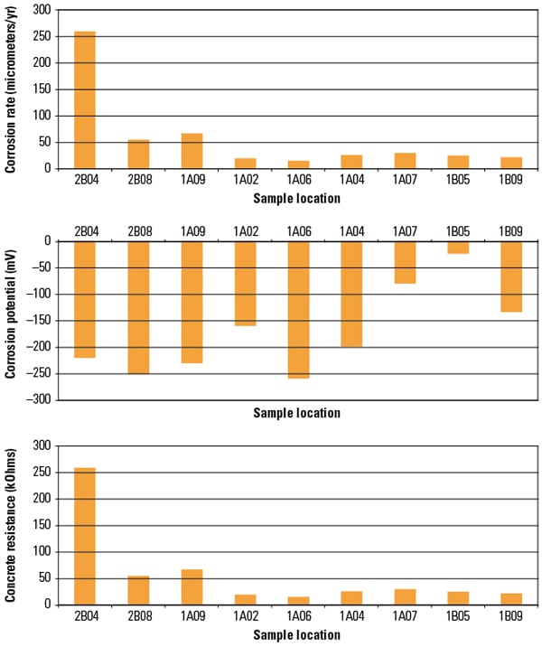 |
| 5. Pre- and post-repair data. Data labeled “2B” are pre-repair values. Data labeled “1A” and “1B” are immediate post-repair values. No data signifies that readings weren’t taken at that location. Source: Restruction Corp. |
Corrosion rate measured in micro-meters per year also showed immediate improvement. Six of seven post-repaired corrosion rates were below both pre-repaired rates. On average, corrosion rate was reduced 80%.
Corrosion potential showed immediate improvement as well. Adjusted for the silver/silver chloride half-cell, copper sulfate electrode readings in the pre-repair were –315mV CSE and –360 mV CSE (CSE or a copper sulfate electrode is used as the baseline). The average post-repair potential was measured at –270 mV CSE. ASTM Standard indicates that for potentials between –200 mV and –350 mV CSE, corrosion is “uncertain.” Readings more positive than –200 mV indicate with 90% confidence that no corrosion activity is present.
Three Years Later
The plant engineering team budgeted additional funds for repair of Unit 2 assemblies to be completed in spring/summer 2008. Three years had passed since completion of Unit 1 repairs. Again, corrosion measurements were taken upon completion. The same two locations on Unit 2 were measured, providing a direct comparison of pre-repair (year 2005) and post-repair readings. Five of the original seven assemblies at Unit 1 were remeasured. This provided a comparison of immediate post-repair and repair-plus-three-years’-time readings. Two new locations at both Unit 1 and Unit 2 were also recorded. Results still indicated that the reinforcing steel was passive, as shown in Figure 6.
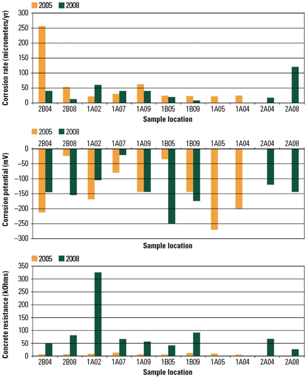 |
| 6. Follow-up test data. Corrosion data collected three years after repairs were made on each set of cooling towers found that the corrosion rates were significantly reduced from the as-found condition. Source: Restruction Corp. |
Concrete resistance increased in both Unit 2 post-repair measurements and Unit 1 measurements recorded in 2008 versus 2005. Average concrete resistance increased over the three-year operation period. Unit 1 resistance increased from 49 kilo-ohms immediate post-repair to 115 kilo-ohms measured three years later.
A U.S. standard has not been developed for corrosion current. However, a proposed Norwegian standard indicates values of 11.5 to 58.0 micro-meters per year would be considered low corrosion. Less than 11.5 micro-meters per year indicates negligible corrosion. The Norwegian standard converts corrosion rate units of micro-amps per centimeters squared to cross-section loss of reinforcing steel using Faraday’s Law.
A low corrosion rate (11.5 to 58.0 micro-meters per year) was found in Unit 1 immediate post-repair measurement in 2005, and the 2008 measurement showed low to negligible corrosion activity. The rebar in Unit 1 remains passive due to the implemented repair scheme. Unit 2 assemblies that were measured prior to repair in 2005 and then again post-repair in 2008 recorded improved corrosion currents in the low to moderate corrosion activity levels.
The corrosion current levels have dropped significantly. Corrosion potentials are also expected to continue improving as the rebar becomes more passive. These results demonstrate that the repairs started in 2000 and completed in 2008 were successful and the towers’ concrete will remain serviceable for many years to come.
— Bruce A. Collins ([email protected]) is vice president of Restruction Corp. Portions of this article are reproduced with the permission of the Journal of Protective Coatings & Linings, published by the Society for Protective Coatings (http://www.sspc.org).