Controlling shaft voltages
The static electrical charges produced by a turbine rotor create an effect akin to the one that results from dragging your feet across a carpet in the winter when the relative humidity is low. Touch a light switch and you usually can draw an arc. Static charges on a turbine rotor are produced primarily by moisture sliding off the last-stage blades. Being lazy, the charges find the easiest path to the turbine case and, under the right conditions, arc to the nearest component, usually the thrust bearing (Figure 1).
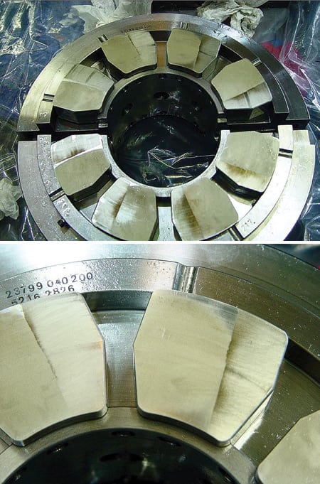
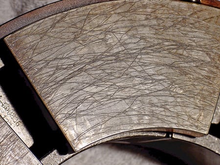
1. Walk a straight line. This is what a thrust bearing of a high-speed turbine looked like after six months of operation without a grounding device. Courtesy: Jim Bothwell Consulting
Ideally, the nearest component is the grounding device that was installed to convey the static charge from the turbine rotor to the turbine case. In most cases—but not always—it restricts the voltage to one or two voltages, so there’s no arc to the turbine case.
Static voltages produced on turbine shafts range from 1 V to 150 V. In one famous case, the shaft voltage on a high-speed (20,000 to 30,000 rpm) turbine reached about 600 volts. The static discharge from the rotor to the case through the bearings was picked up by the proximity probes on vibration-monitoring equipment in the control room. An inspection found that the turbine and compressor had large clearances filled with lubricating oil that has exceptional insulating properties.
The unit was not equipped with a shaft-grounding device. To compensate, engineers installed a ground strap, which eliminated the spikes detected by the vibration monitoring equipment and reduced the amplitude of the static discharge voltage to 0.01 volts. Lost in the annals was how much damage was sustained before the turbine was properly grounded.
Circulating currents
The two primary types of damage to babbitt bearings are "frosting" and "turbine worms." Turbine worms or "worm tracks" are also found on welded teeth of geared couplings and gearboxes. They are most often caused by electromagnetic currents or circulating currents produced by magnetic fields in rotating equipment (Figures 2 and 3). It’s current, rather than voltage, that damages a bearing. But because measuring the current through the shaft is impractical, we measure the magnitude of the voltage instead.
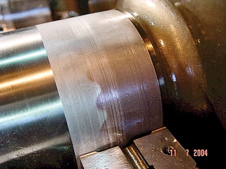
2. Decorated shaft. A "frosted" gearbox shaft. Courtesy: Jim Bothwell Consulting
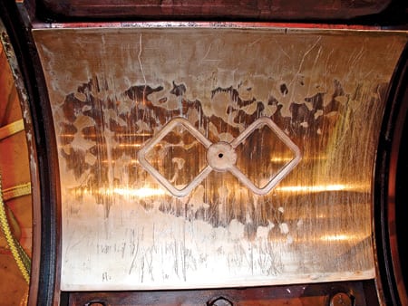
3. Modern art. Frosting on a babbitt bearing section. Courtesy: Jim Bothwell Consulting
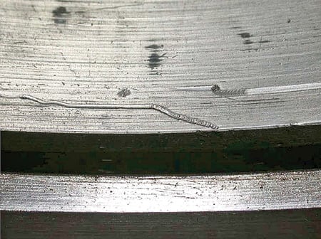
Under a 30X microscope, a turbine worm looks like small weld beads. Damage to roller and ball bearings appears as fluting-like ripples (such as those seen on a poorly maintained gravel road) or spalling of the bearing race. Gears and couplings can experience "welding" or "arc" marks on the teeth, or as pits or frosting (Figure 4).
5. Bad infestation. Here are typical turbine worms created by electromagnetic activity across the shaft-bearing interface. Notice the arc weld bead effect on the bearing. Courtesy: Jim Bothwell Consulting
6. Night crawlers. With these worm tracks on the thrust bearing of a high-speed compressor, note the change of direction of the electrical tracks. Dirt or contamination would cause straight lines. Courtesy: Jim Bothwell Consulting
Production of an AC voltage requires three elements: a magnet or a magnetic field, a coil of wire, and relative motion. AC current is produced when the AC voltage is given a complete or circular electrical path. In the case of a turbine or compressor, the rotation of the shaft provides the relative motion, and the turbine blades (with their shrouds and/or lashing wires) provide a loop or coil between each blade.
The missing element, a magnet or a magnetic field, is most often supplied by technicians performing magnetic particle testing of turbine blades or compressor components. The technician wraps a few turns of cable around a particular blade group or component and then energizes the cable with a high-amplitude DC current. Once the DC current establishes a magnetic field, the technician sprays Zyglow or some other product on the component and examines it under a black light to see if there are any indications of cracks or imperfections in the surface of the material. Each crack will produce a glow where a north and south pole were formed on the sides of the crack by the strong magnetic field.
After the DC supply has been turned off, the turbine or compressor component retains a certain amount of magnetic field or gauss that depends on the strength of the magnetizing DC current, the number of cable turns or wraps, and the permeability of the component material. The residual gauss is produced by the alignment of polar molecules in the material. Removing it requires returning the molecules to the random state in which they existed prior to the testing.
Some magnetic particle inspection technicians believe that they can restore the particles to their prior state (a process known as degaussing) by reversing the polarity of the DC current in the wrapped cables for a duration equal to the time of its energization. That may happen, but I’d bet that the technician has a better chance of hitting the lottery.
Circulating currents are produced in the rotor and stationary components of a piece of turbomachinery when it is operating. They can result from the residual magnetic fields in the components of a turbine, compressor, or pump. In general, circulating currents are of low voltage but of high current amplitude. If there are large gaps between the rotating and stationary components or insulators on the bearings, an arc will not form but the AC voltage will exist on the component, waiting for a chance to complete the electrical circuit.
Turbine, compressor, or pump components also can be magnetized by:
- Placing magnetic base tools on components.
- Allowing coils of "stinger" or ground cable from a DC welder to rest on, or be close to, a component while welding is taking place.
- Holding a component in place with a magnetic field so it can be drilled or machined.
All turbine or compressor or pump components should be degaussed to a level of less than 2 gauss following magnetic particle testing or any other activity that places a magnet or magnetic field on or near the components. Bid specifications for the following activities and equipment purchases should include the requirement that all components be degaussed to less than 2 gauss:
- Magnetic particle testing.
- Nondestructive testing.
- Inspection or repair work that includes welding or the use of magnetic base tools.
That may seem a lot of trouble to go to every time a pump is overhauled, but experience teaches otherwise. Here’s an example.
A 5-hp pump failed at a refinery and required repair work on the impeller and case. The pump was sent off-site to the shop for the repair. The pump was returned, installed, and operated for about nine months before the bearings failed. The pump was removed from service a second time, new bearings were installed, and it was returned to service. About six months later, the bearings failed again. This time, the bearings were examined using a 30X microscope, which revealed the telltale worm tracks of a magnetic field. The pump then was sent to the shop to be disassembled, degaussed, and returned to the plant. It later was reinstalled and has been in continuous operation for the past five years.
Batteries not included
Does your turbine-generator run on batteries? Probably not, but an "AC battery" or AC potential exists on the shaft between the generator and brushless exciter of small units, and on the entire brushless exciter shaft of large units. That’s why generators and exciters have insulated bearings.
Consider another case history (more can be found in our May WEB EXCLUSIVE). The AC potential on the bearing pedestal of one 800-MW generator was measured at about 40 V with a handheld multimeter. The setup used a carbon brush taped to the end of a broom handle and a "capture and hold ammeter"; 18 AWG test lead was used to determine the bearing pedestal to ground current on a "touch and read" basis. When the carbon brush contacted the exciter bearing pedestal, there was an instantaneous flow of 150 amps. Leave this test to the pros; the 18 AWG wire served as an excellent fuse, as it promptly vaporized on contact.
As a practical matter, do not perform ground current measurements on brushless exciters. Also, never attempt to ground the shaft between the generator and exciter or the exciter shaft. Maintaining insulation between bearings and case and insulated couplings is the key to avoiding "AC battery" problems.
VFDs: A special case
The downstream bearings and gears of some types of rotating equipment can become pitted, frosted, or spalled even if they are not part of the drive train. In newer variable-frequency-drive (VFD) units that use solid-state controllers to decrease signal switching, electrical spikes on shafts can find their way to ground through the unit’s bearings. Motor manufacturers were the first to recognize the phenomenon, and they responded by insulating both bearings. Manufacturers of gearboxes were next to notice the problem, but it has taken them longer to address it.
In one recent case, vibration increased on the turbine of a turbine-compressor-generator set that had been in operation for less than six months. The set consisted of a steam turbine, an insulated coupling, a gearbox, an insulated coupling, a multistage compressor, and a generator with a brushless exciter. When the turbine shaft began vibrating, the unit was shut down for inspection and repair. The turbine bearings were reported as having been frosted, and they were replaced during the forced outage. When the unit was restarted, plant personnel reported rapid deterioration of its bristle-brush grounding device, which proved unable to keep the shaft voltage near zero. The installation of an auxiliary ground strap reduced the static charge on the shaft to 0.01 volts.
Apparently, the gearbox manufacturer had either installed, or insisted on the retrofitting of, insulated couplings on both the drive and driven side of the gearbox. In this case, the static discharge from the steam turbine due to inadequate grounding made its way to the turbine case through the turbine bearings, and not through the bearings or gears on the gearbox.
Insulated couplings should be considered or installed between any motor driven by a VFD unit and downstream components, as well as between any static charge–producing drive unit and downstream components. That’s especially true for any specialty gearboxes or for any equipment that uses roller or ball bearings.
Some end users have installed grounding devices on the shafts of motors driven by VFD units in an attempt to prevent damage to downstream bearings. In each case, the device did not prevent damage to downstream bearings. It is not known if the grounding devices were not functioning correctly, or if any shaft voltage measurements were obtained to verify their performance.
Other mechanisms have been known to produce an increase in shaft voltage or shaft-to-ground current. They include unbalanced electrical circuits in motors or generators (caused by turn-to-turn shorts in the stator), unbalanced magnetic fields in a generator rotor (caused by turn-to-turn shorts in it), and the failures of diodes on brushless exciters or static excitation systems. You’ll need to research those on your own.
Staying well-grounded
Although they are in common use, the terms "grounding brushes" and "grounding devices" are actually misnomers. Each has the same purpose: to convey static charge from the turbine shaft to the turbine case and not convey static charge from the shaft to station ground.
There have been cases in which plant personnel installed wires to connect the grounding brush on their steam turbine to the station ground two floors below. They had the best of intentions but the wrong solution. Because arcing or sparking occurs between the rotor and the bearings or seals within the turbine’s case, the circuit must run directly from the shaft to the case. The grounding device in contact with the rotor must first make contact with the case. The next step is to provide a connection from this connection point to station ground.
Several types of grounding devices are commercially available. They include:
- Carbon brushes
- Copper-impregnated carbon brushes
- Braided copper straps
- Braided copper straps with spring assists
- Braided copper straps with weights on one end
- Bristle brushes
- Braided welding cables
- Copper ground straps
Each has strengths and weaknesses and a price that ranges from a few dollars to a few thousand dollars. All grounding devices, regardless of the type or manufacturer, require the maintenance and monitoring of shaft voltage to ensure that the rotor and case remain at the same electrical potential. There does not appear to be a single grounding device that works for all equipment or all environments. Personnel at each plant should evaluate and select the grounding device based on the performance of the device at their location. For this reason, a high price is not necessarily an indicator of high performance in your application.
The maintenance requirements for shaft grounding and shaft voltage sensing are likewise site- and application-specific. At one plant, where technicians remove and clean one of the four bristle brushes on one unit every single day for cleaning, shaft voltages remain below 1 volt, as verified by a handheld meter reading. At another plant, technicians began by checking ground straps every week but then backed off to once every two weeks and, later, to once a month and then once every six months. Although they later installed shaft voltage–monitoring equipment that sends signals to the control room, the techs at this plant still routinely check shaft voltages with a handheld device.
I carry ground straps with me when checking shaft voltages on rotating equipment. In most cases, I find elevated shaft voltages, indicating that the existing rotor grounding device is either missing or not functioning correctly. If that is the case, I fabricate a ground strap and bracket and throw it over the shaft. This almost always reduces the shaft voltage to 0.001 volts, buying time to identify the problem and its solution. In every case, the customer leaves my ground straps in place to maintain the shaft voltage at or near 0.01 volts.
Locating grounding devices
The grounding devices on most turbine-generator sets are located on the bearing cover of the turbine closest to the generator. Some units have grounding devices in the governor pedestal. Because the turbine-generator shaft consists of solidly bolted couplings between each of the train components, one, two or more grounding devices can be located at a single point on the turbine shaft from the governor pedestal to the coupling between the turbine and the generator. The same can be said for turbine-compressor sets with solidly bolted couplings. I advise locating the grounding device(s) near the low-pressure turbines on turbine-generator sets and near the turbines on turbine-compressor and turbine-pump sets.
The same situation applies to trains containing gearboxes. In some cases, a turbine that drives a generator through a gearbox has a grounding device that is installed between the gearbox and the generator, or attached to the generator end shield. Any static charge on the turbine shaft must pass across the teeth of gears in the gearbox to get to the grounding device and hence to the turbine case. These arrangements, which were part of the unit’s design package, clearly did not consider the electrical path. Moving the grounding device to the turbine shaft would allow static charge from the turbine shaft to pass to the turbine case without passing across the teeth of the gearbox.
There have been instances where braided ground straps have been used on gears located in the governor pedestal of a turbine-generator unit to remove static charge from the rotor. The static charge passed through the gear teeth to get to the turbine case. The resulting pitting made the gears unusable. To correct the situation, the braided straps had to be moved so they contacted the rotor.
Taking shaft readings
In the U.S. market, instruments are available to simplify measurement of shaft voltage and shaft-to-case current. All such instruments rely on the contact between a grounding device and the rotor, or the contact between a sensing device and the rotor, for their input. Because all grounding devices and sensing devices currently available require some degree of maintenance, there is always the need to verify readings of an installed instrument by a handheld instrument capable of measuring shaft voltage or shaft-to-ground current.
The key to installing instruments is to first establish a baseline and then choose the setpoint or alarm to trigger upon deviation from that level. Establishing the baseline includes verifying the performance of the grounding device or shaft-sensing device.
The amplitude and frequency of static shaft voltages are too great for most standard handheld multimeters to handle. Such instruments require real RMS output indications. Because they read the average of the signals within the instrument’s sampling period, they do not capture the high voltage spikes or peaks of static voltage produced on rotors of rotating equipment. Voltage meters must be able to measure voltage at over 400 Hz. Although the voltages produced by electromagnetic effects inside equipment are only a few volts in amplitude, they are usually at a high frequency that a standard multimeter cannot deal with.
You can use a handheld device to measure the shaft voltages on a piece of rotating equipment, but doing so requires probing the shaft directly. Accordingly, use extreme caution when using a handheld instrument that contacts the shaft.
—Jim Bothwell is the principal of Jim Bothwell Consulting. He can be reached at [email protected].