Considerations When Upgrading Gas Turbine HMIs
Aging human machine interface (HMI) hardware will eventually become a burden on plant operation. Obsolete HMIs can cause problems with connectivity, historical data loss, and hardware failure. As the hardware ages, the availability of replacement parts decreases and the cost for these parts increases. Hard-to-find motherboards with archaic ISA slots and obsolete ISA ARCNET cards can make upkeep of these machines very difficult and costly. There comes a time when replacing the entire HMI becomes a necessary and viable option, particularly when considering reliability and maintenance costs.
Site Layout
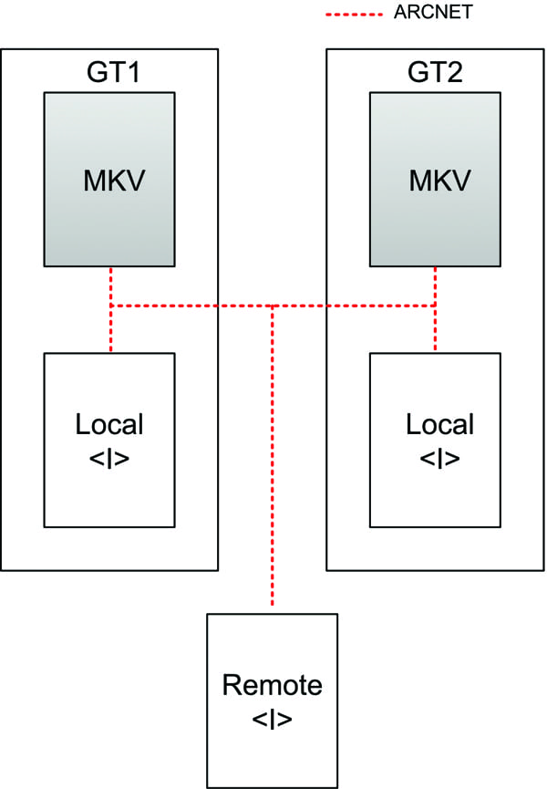
Recently, a peaking power plant replaced its aging HMI system. The site had two GE Frame 6B gas turbine generators controlled by two GE Speedtronic Mark V control systems. These units were used for fast-dispatch peaking operation and typically were started every day during summer peak, running for 3 to 4 hours each day. There were two local and one remote DOS <I> operator interfaces. The existing Mark V Stagelink network architecture had three <I>s, configured such that each <I> was able to communicate with both of the Mark Vs (Figure 1).
The existing <I> was a product of the 1980s and was designed in the DOS operating system. This obsolete technology had quite a few hardware and software limitations. The <I> software was no longer user friendly and offered no historical data storage (historian) capabilities. The driver for the replacement was that the equipment was so old it was failing and the units could not be operated easily without this interface. This impacted the customer’s ability to dispatch the units. All of the hardware components in the <I> were obsolete, and migrating the software to a modern PC environment was very difficult.
Although the old system was being completely replaced, the customer needed all of the functions from the original <I> to be carried over to the new system. The customer also required:
■ Easy access to tools such as EEPROM download, dynamic rung display, logic forcing, and valve calibration.
■ Off-the-shelf, commercially available hardware.
■ Display screens equivalent to the existing ones, with all important data displayed and easily viewed.
■ Accurately time-stamped alarms and diagnostics, readily available for troubleshooting.
■ Easy connectivity to devices other than the Mark V.
System Design
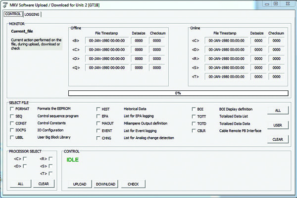
The upgraded system was built around the Turbine Monitoring System (TMOS) available from Turbine Technology Services Corp. (TTS). All of the existing tools were included in the new software. In TMOS, EEPROM download, dynamic rung display, sequence editor, logic forcing, valve calibration, pre-vote data display, control constant adjust, IO configurator, and ARCWHO are all Windows-based functions and easy to operate (Figure 2).
The hardware selected for the servers was state-of-the-art, off-the-shelf equipment, easily obtainable commercially. The multi-core processors and hot-swappable hard disks ensure durability and reliability. Redundant power supplies ensure that the server will continue operating in the event of a power supply failure. The client computers are robust and can drive multiple monitors to provide space for the multi-screen environment.
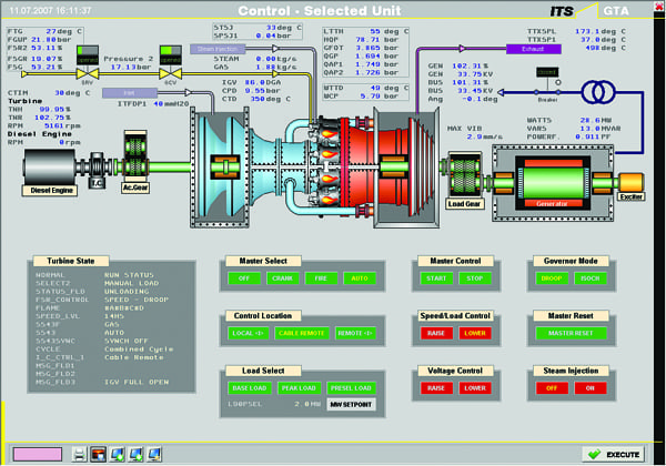
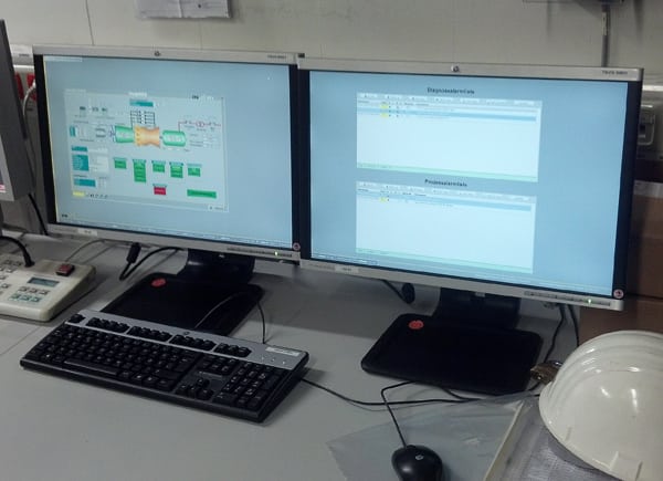
The various screens display the pertinent unit information in an easy-to-read fashion (Figure 3). By clicking on a value on the screen, the user has access to all of its information such as scale, engineering units, description, calibration reports, and associated connection drawings. This makes troubleshooting much quicker and easier. Screens can be resized and placed anywhere the user wants. This allows for multiple screens to be opened and viewed at one time on multiple monitors (Figure 4).
All events, alarms, and diagnostic alarms are stored with millisecond resolution on the hard drive. The new log viewer tool replaces the need for the old dot-matrix printer. Retrieval of alarms can be easily managed with the log-style viewing tool. The historical events log can then be printed in report style or saved as a PDF.
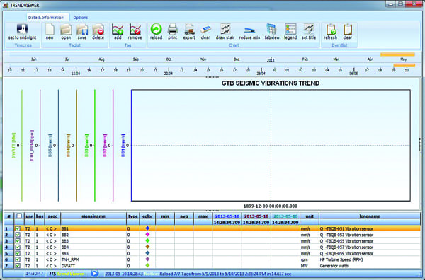
An additional function of this system is a trend viewer coupled with a historian. The trending tool allows trending from both real-time signal values and historical signal values. Signal values from the screens can be dragged and dropped into the trend viewer and their values displayed (Figure 5).
The smart log uses compression algorithms to store large amounts of collected data in a small amount of space on the hard drives. Months of data can be stored on the HMI RAM, which makes for very fast access times when reviewing historical trends.
The customer also requested that the new HMI system gather data via Modbus from a separate device. (Modbus is a simple yet robust communication protocol developed in 1979 that is used extensively, even today, in the industrial environment.) This was accomplished by the TMOS software, which can act as either a Modbus slave or a master. If necessary, it can also connect with devices using other protocols such as GSM, ProfiNet, or OPC and can communicate with programmable automation controllers and Bently Nevada vibration systems.
Network Architecture
The new system offers redundancy in both the servers and the network. It is based on a client/server architecture that is both reliable and robust. The servers are used to communicate directly with the Mark Vs, while the clients communicate solely with the servers, reducing overall traffic and reducing the communications load on the <C> core of the Mark V (Figure 6). With this structure, the server can connect to up to 16 Mark Vs at once, which makes it highly scalable.

The new network layout offers redundancy for both the data servers and the clients. Redundancy is key to creating a robust system that can withstand hardware failure. The TMOS system has automatic failover capability, where the clients sense when their connection to the server has been lost. This could be caused by a multitude of issues, including severed network cabling or failed network cards. The clients can automatically and seamlessly change servers and continue to function, while maintenance can be performed on the faulty server.
Hard drive failures are always a possibility, and if the system has not been designed correctly or regular backups have not been made, they can be catastrophic. This issue was addressed in the new system by use of a redundant array of independent disks (RAID), in this case RAID5. If any single drive fails in the server, the RAID controller can rebuild the information that was on that drive, making the failure invisible to the end user. An indication from the hard drive controller alerts the user of the problem, and the offending hard drive can be hot swapped with a replacement drive without needing to take anything offline.
Smooth System Installation
The entire upgrade was performed without requiring an outage. This was possible because the new HMI computers were installed and commissioned alongside the old HMIs and were operated simultaneously. The new HMI was brought online, commissioned, and tested in operation for some time before the old HMI was decommissioned. Thus, no HMI or control system downtime was necessary. The new system utilized the original site files in the unit directory. These files were parsed and used by the TMOS software. Much of the new HMI setup and configuration was performed before the hardware was shipped to the site, reducing required site time and thus reducing costs.
In order to ease the transition to the new graphics and learn the new system, the old HMIs were left in place for a few days while the customer was given training on the newly installed machines. At the end of this period, the old HMIs were decommissioned and removed. Also during this training period, the graphics were tuned to suit the customer’s needs. An important part of any HMI replacement is customization of the graphics to meet expectations and unique preferences particular to each site. ■
—Contributed by John Sprague, senior project engineer with Turbine Technology Services Corp., Orlando, Fla.