Condenser Tube Life-Cycle Economics
There are literally miles and miles of tubing in every power plant that will operate very reliably for many years. However, much of that tubing will spend much of its life in the most demanding of high-pressure and high-temperature service, exposed to superheated steam and chemically treated water that can reduce the expected life of the tubing. Most tubing will, at some point during the operating life of the plant, require replacement. The challenge for the plant operations staff is to understand the possible material failure mechanisms and keep an eye on those exchangers beginning to show signs of tube failure.
Copper Tube Failure Mechanisms
A number of potential failure mechanisms are possible in power plant heat exchanger tubing. To compound the identification challenges, the failure mechanisms common in copper alloys are quite different than those for stainless steels and high-performance alloys.
First we look at copper alloys, commonly used in power plant feedwater heaters and condensers. The most common damage mechanisms for copper alloys from the steam side are ammonia grooving and stress corrosion cracking.
Ammonia Grooving. When hydrazine and similar derivatives are used to assist with oxygen scavenging, these degrade into ammonia compounds. Admiralty, aluminum brass, and, to a lesser extent, 90-10 copper nickel, are sensitive to selective corrosion by ammonia compounds. As these are considered noncondensables, the steam drives them into the center of the condenser, the air removal zone. The ammonia combines with the condensate and concentrates on the support plates, running down the surfaces. The ammonia solution attacks the tube surface adjacent to the support plate, creating grooves.
Stress Corrosion Cracking (SCC). When the tubing has high residual stresses, another mechanism can speed the failure process, stress corrosion cracking (SCC). Both admiralty and aluminum brass are susceptible to ammonia-induced SCC. The stresses are commonly developed during the tube-straightening operation during manufacturing. This failure mechanism can occur quite rapidly. A condenser having tube failures caused by both ammonia grooving and SCC is not uncommon.
The failure mechanisms on the cooling waterside of the heat exchanger are remarkably different, given the lower temperature levels and cooling medium. The mechanisms are usually erosion, corrosion, or a combination of the two.
Erosion-corrosion. Copper patinas formed under water are usually oxy-hydroxide based and are soft. High water velocities can erode the soft patina, exposing the base metal below. A new patina then reforms, and when it reaches a critical thickness, the cycle repeats. This is called erosion-corrosion. For admiralty and aluminum brass, the commonly accepted maximum water velocity to prevent this mechanism is 6 feet per second. However, it is common to see failure in localized areas, although the average velocity may be less than 6 feet per second.
Turbulence causes localized high velocity; a common example is inlet end erosion. Local obstructions, such as mollusk shells, can also cause localized high water velocity, resulting in very quick failure. It is not uncommon to experience tube perforations due to this cause within a few days of inlet screening problems.
H2S and Sulfuric Acid Attack. Low pH and the presence of sulfur compounds will dissolve protective patinas, exposing fresh metal. This causes corrosion rates to increase several orders of magnitude. Polluted, stagnant waters create hydrogen sulfide generated from the decomposition of marine organisms. When H2S is present, the copper patina cannot reform its protective surface. Today, new power plants are rarely permitted to use clean fresh cooling water, so treated wastewater has become one of the few cooling options available. When cooling water sources are switched from fresh to treated wastewater, 90-10 copper-nickel tubing failures often start within six months of the change. Even water containing relatively inert sulfur ions can become aggressive when sulfate-reducing bacteria are present. The sulfate-reducing bacteria will convert the sulfate ions into a more aggressive species, such as H2S or sulfuric acid.
General Corrosion and Copper Transport. The patina that forms on admiralty brass, aluminum brass, and copper-nickel is porous and allows copper ions to gradually diffuse into the water, even under the best conditions. Copper ions are toxic to many aquatic organisms. This is the key reason that copper-based paints are placed on marine structures to prevent biological fouling. As the copper dissolves, the tube wall gradually thins. When water conditions are ideal, dissolution rates are slow and 25-year tube life is typical. However, the copper transport can still be significant enough to have an impact at other locations. For example, the tubes removed from a typical 300-MW condenser with admiralty tubes at the time of replacement will weigh about 50% of the original approximately 400,000-pound tube weight. This indicates that the 200,000 pounds of copper alloy has dissolved.
Where does this dissolved copper go? Both the condensate and the cooling water discharge are candidates. Copper concentrations in condensate can range from 0.2 to 10 ppb, depending upon location. Although this concentration appears to be very small, when one considers mass flow rates of millions of pounds per hour range, the overtransport can be quite significant. In the closed steam side, it deposits at locations where steam has an abrupt change of volume.
Depending upon the plant design, the copper lost may often plate out on the boiler tube surface (Figure 1) or on the high-pressure steam turbine blades. When the copper plates on the boiler tubes, it can initiate catastrophic liquid metal embrittlement of the steel. The situation is aggravated as the deposit layers, shown in Figure 1, act as an insulator, raising the boiler tube temperature. When the copper is in direct contact with the boiler tubes, the melting point can drop to as low as 2,012F, where the typical steel melting temperature is 2,700F. When the copper plates on the turbine blades, the turbine efficiency drops and the overall plant output is restricted.
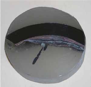
1. Alternating copper metal and iron oxide layers on boiler tube illustrate how corrosion can release copper into the steam circuit of a boiler or into the cooling water from a condenser. Courtesy: Gary Hoffman, “Chemical Cleaning of Natural Circulation Boilers: The Good, the Bad, & the Ugly” (Southwest Chemistry Workshop, Scottsdale, Ariz., July 2005)
On the cooling water side, the federal discharge limit in most areas is 1 ppm, a relatively easy target to meet unless the tube is actively corroding (Figure 2). However, in many localities, regulators are recognizing that 1 ppm in the hundreds of thousands of gallons per minute of water discharged can add up to a significant amount of copper. In those regions, limits of 40 ppb or less have been imposed. This target is significantly tougher and may require expensive polymer treatments to reducing the corrosion rate.
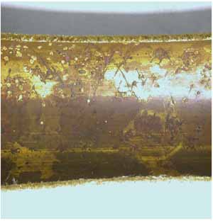
2. Copper alloys in condenser tubes often experience ammonia stress corrosion cracking and grooving. On the cooling water side, these same tubes experience erosion and corrosion when water velocities exceed 6 fps and pitting and under deposit corrosion. Courtesy: Plymouth Tube
Stainless Steel Tube Failure Mechanisms
All stainless steels, both the commodity grades (TP 304, TP 316, and derivatives) and the higher-performance versions, are resistant to the majority of boiler chemicals, including all of the hydrazine derivatives. At higher temperatures, one mechanism does cause premature failure: chloride stress corrosion cracking (Figure 3).
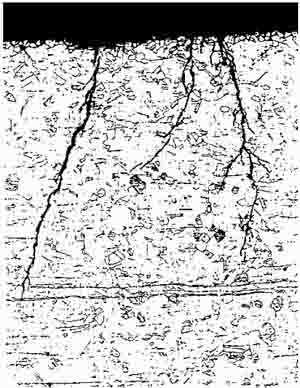
3. The steam side of this stainless steel tube has experienced stress corrosion cracking at the surface. Courtesy: Plymouth Tube.
Stress Corrosion Cracking. Stainless steels containing 2% to 25% nickel are susceptible to cracking when a combination of stress, chlorides, and temperature are present. Those containing 8% nickel (TP 304) are most sensitive (Figure 4). The minimum critical temperature for TP 304 is approximately 150F. Because the metal temperature in condensers and lower-temperature balance-of-plant exchangers is below the critical temperature, it is extremely rare for TP 304 and TP 316 tubing to fail from this mechanism.

4. Time to failure of Fe, Cr, and Ni wires in boiling magnesium chloride illustrate the effect of nickel on chloride stress corrosion cracking in stainless steels. Source: Plymouth Tube
SCC can occur in feedwater heaters when the steam chemistry has had a chloride excursion. Usually, this occurs when a condenser tube leaks and the plant continues to operate. The damage can be extensive, sometimes requiring replacement of the heater. The failure mechanism has also become more common in plants that have switched from baseload to cycling modes. The chlorides concentrate in regions that alternate between wet and dry, primarily in the desuperheating zone or in the adjacent area of the condensing zone.
The cooling water side of stainless steel tubes are exposed to a different set of failure mechanisms.
Pitting and Crevice Corrosion. TP 304 and TP 316 are susceptible to pitting, crevice corrosion, and microbiological influenced corrosion (MIC)–related crevice corrosion in many waters normally considered benign. TP 304 and TP 316 should not be considered if the cooling water has chlorides that exceed 150 ppm and 500 ppm respectively (Figure 5). An expert should also consulted if the manganese levels are higher than 20 ppb or iron levels exceed 0.5 ppm. Like copper alloys, TP 304 and TP 316 should not be considered retubing material candidates if treated wastewater is the cooling water source.
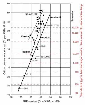
5. Critical crevice temperature and maximum chloride levels versus PREn illustrate the pitting and crevice corrosion resistance of various stainless steels. Source: Plymouth Tube
While not explicitly a material failure mechanism, condenser tube fouling is a common cause for increasing heat rates and can be expensive to repair. Fouling can be due to either biological factors or scaling. The layers are thermal barriers that raise steam saturation temperature and turbine backpressure. Condenser tube fouling can easily cause an annual increase in fuel cost of $250,000 for a mid-sized coal-fired plant.
Potentially a bigger concern is the damage of the tubing under the fouling deposit due to underdeposit or crevice corrosion. Once the surface is covered, it is no longer flushed with the bulk cooling water and contaminates, such as chloride or sulfur, concentrate. With a drop in pH, the acidic condition attacks the passive surface layer, initiating a corrosion cell. As this cell encourages further concentration, attack can be very rapid. It is not unusual to experience through-wall attack in three weeks on an improperly laid-up 0.028-inch-thick TP 304 condenser tube.
Scaling—due to the heating of cooling water saturated with calcium carbonate, gypsum, or silica—can precipitate surface deposits that can significantly lower heat transfer. These constituents have inverse solubility, meaning that they become less soluble as the water temperature increases. Often, the deposits are thicker in the latter passes, or higher-temperature section of the condenser. It is common in some plants with cooling towers or cooling lakes with high evaporation rates to see cleanliness factors, when calculated by the HEI Condenser method, to be in the 50% to 65% range.
How About Titanium?
Titanium grade 2 is normally considered immune to any of the pitting and crevice corrosion mechanisms common in the power generation cooling circuits. One exception may be the crystallization equipment used in zero-discharge plants. In this equipment, grades 7 or 12 may need to be considered. However, because of its low modulus of elasticity, titanium can be susceptible to vibration damage if the heat exchanger is not properly designed.
The Value Comparison
Many operations do not calculate the increased costs related to a problem heat exchanger in addition to the capital and installation costs of replacement tubing. Justification for your cleaning and/or retubing starts with a defendable value comparison summary. The summary should depend upon a life-cycle basis and not solely on the lowest initial cost. Your company must select the length of the life-cycle calculation, as many coal-fired plants that have operated for 30 years may have another 20 years of expected operating life remaining.
The life-cycle cost calculation will have several cost items that must be developed, including:
- Initial tube cost
- Installation costs
- Fuel savings based on higher thermal performance
- Lower cooling water chemical treatment costs
- Reduction of lost generation due to turbine efficiency losses
- Reduction or elimination of boiler tube and high-pressure turbine cleaning costs
- Elimination of emergency outages and/or derates to plug leaking tubes.
Condenser Retubing Case Study
The following case study provides an example for how to compare the true cost of running with existing, poorly performing tubing with the cost of retubing a condenser. The approach applies equally as well to a feedwater heater or other balance-of-plant heat exchangers.
Consider a condenser for a 300-MW coal-fired plant that currently uses 16,400 one-inch OD x 18 BWG (0.049 average wall thickness) 90-10 copper nickel tubes that have an effective length of 42.2 feet. The steam load is 1,480,000 lb per hour at an enthalpy of 950 Btu/lb. On this unit, the turbine exhaust area is 375 square feet. The circulating pumps provide a design flow of 114,000 gpm through the tubes that develop a design head loss of 19.58 feet. At this time, 6% of the existing tubes are plugged. Scaling is minimized through aggressive water chemistry controls providing a Heat Exchange Institute (HEI)–defined cleanliness factor of 85%. The condenser was designed for an inlet water temperature of 85F, which is a common inlet water temperature in early summer and early fall. However, it can be higher during mid-summer.
In our model calculation, tube leaks are now occurring approximately twice per year, particularly during peak summer season (hotter temperatures increase corrosion rates). Every four to five years the high-pressure steam turbine must be cleaned due to copper plating on the turbine blades. During this period, the total drop in plant capacity is 21 MW.
The original tubes lasted 22 years, but because of change in cooling tower operation and new water sources, the expected life of the new 90-10 copper nickel tubing may only be 10 to 15 years. As this is a closed-loop cooling tower plant, the service water has been chemically treated with ferric sulfate to assist repassivation of the copper nickel after excursions of cooling water chemistry when trying to keep the tubes and cooling tower clean. This cooling water is aggressive to many alloys, so picking an alloy resistant to high chlorides and MIC is paramount. The alternative candidates that this utility is considering are titanium grade 2, AL6XN high-performance austenitic stainless steel (UNS N08367), and SEA-CURE (UNS S44660) high-performance ferritic stainless steel, all proven to have a good track record in similar water. (AL6XN is a registered trademark of Allegheny Technologies; SEA-CURE is a registered trademark of Plymouth Tube.) TP 304 and TP 316 are not candidates for this condenser, as the chloride levels commonly climb over 700 ppm, and Mn and Fe levels are high.
The HEI Standards for Steam Surface Condensers are an excellent basis for comparing the thermal and mechanical performance of the various tube materials. In addition to determining backpressure, the potential for vibration damage, and changes in uplift can also be evaluated. Initial results of the analysis are included in Table 1. Each of the following sections relates to a line item in the table.
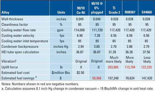
Table 1. Comparison of thermal and mechanical properties of various condenser tube candidates for a 300-MW unit using HEI Standards for Steam Surface Condensers. Source: Plymouth Tube
Wall Thickness. When titanium or stainless steel tubing is selected for a condenser retubing, it is common to choose 22 BWG (Birmingham Wire Gauge) or 0.028 inch. Stainless steels have a higher modulus of elasticity than copper alloys. Because of the higher modulus, thin wall stainless tube can be as stiff as the thicker-walled copper alloy. This minimizes the impact of vibration.
Cleanliness Factor. Although titanium’s modulus of elasticity is lower than that of copper alloys, the high material price requires titanium to be used in thin walls as well. This requires a change in design philosophy. The thicker copper alloy ID and OD tube patinas require the designer to use lower cleanliness factors than if stainless steel or titanium tubes were selected. Compared to 85% commonly measured for clean copper alloys, the stainless steels and titanium traditionally exhibit HEI cleanliness of 95% or better. In many cases, the stencil on stainless and titanium tubes that may have been in service for several years may still be read. For our calculations, 95% is used.
Cooling Water Flow Rate. Although the original design flow was 114,000 gpm, flow will vary as the head loss changes. The low-head/high-volume circulating water pumps have mass flow rates that are highly sensitive to head loss. For example, the 1.5-foot head increase caused by plugging 6% of the tubes may typically result in a 2% decrease in cooling water mass flow. Conversely the 3-foot head decrease by changing to 0.028-inch wall thickness tubing from 0.049-inch wall original tubing can typically result in 3% to 4% increase in mass flow. We’ve included 3% in our calculations to be conservative. If available, the specific pump curve(s) for the plant should be used.
Cooling Water Velocity. The cooling water velocity is calculated from the cooling water flow rate and the inside diameter of the tubes. The water velocity is used to determine the temperature rise in the tube. Although normally considered to have a significant impact on the condenser performance, the cooling water mass flow is the key factor for removing heat.
Cooling Water Inlet Temperature. In this analysis, we’ve used the design inlet water temperature for the basis of the calculations. When the plant has an undersized condenser that is condenser-limited during peak summer conditions, you might want to consider using the maximum inlet water temperature for your analysis.
Condenser Backpressure. After the cooling water, steam flow, and tube alternative parameters have been determined, the saturation temperature is calculated and the backpressure is found using the steam tables. A lower backpressure, or better vacuum is desired, which increases turbine efficiency. For this condenser, the 6% plugged tubes created a backpressure increase of 0.06 inch Hg. HEI predicts a very significant backpressure drop of 0.16 inches for titanium and slightly lower 0.15 inches for the superferritic S 44660. With higher thermal conductivity, the drop in pressure for the superaustenitic N 08367 is approximately half, at 0.08 inches.
HEI Tube Span Calculation. Over the years, many different vibration methodologies have been developed to calculate a “safe span” that results in no tube damage. Each of these uses a different series of assumptions. The HEI span reported in Table 1 assumes that the condenser tube will vibrate and that the support plates shall spaced to keep the vibration amplitude equal to or less than one-third of the ligament spacing. When two adjacent tubes are vibrating, the design allows for an additional clearance of one-third of the ligament preventing tube-to-tube collisions.
Although the absolute value for a safe span for a specific tube material may vary significantly, depending upon the method used, the different methods are in relative agreement of the proportional span relationship between alloy and wall for the same OD. If the specific method predicts a longer span for a proposed tube selection, this alternative is considered more conservative, or safer. If the method predicts a shorter span, the alternative selection is riskier.
In this analysis, HEI predicts a span of 36.87 inches for the Cu-Ni. The calculated span for titanium is almost 5 inches shorter, suggesting that the risk of vibration damage is high, unless other preventative measured are taken. N08367 has a slightly shorter calculated span, which suggests a slight increase in risk for vibration damage. Only the S44660 has an HEI calculated span longer than for the Cu-Ni. The most common solution to preventing vibration problems is the installation of “stakes” mid-span between the support plates. Wedged between the tubes, the stakes are additional supports.
Uplift Force. Copper-nickel has the highest metal density of any traditional condenser tube material. When combined with the thick initial wall thickness, all of the alternatives will result in a condenser of significantly less weight. The difference in pressure across the large turbine exhaust area can create significant uplift. When this condenser is at 1.5 inches of backpressure, the uplift due to the vacuum is approximately 700,000 lb. If another tube is selected, the drop in tube weight could result in damage to the supports. Switching to titanium tubing results in a weight reduction of 204,000 lb. If titanium is selected, the specialist should be consulted to check if reinforcements are needed in the anchoring areas.
Estimated Fuel Savings. The change in backpressure will have an impact on heat rate and, ultimately, the amount of fuel that will be used. As this is a coal-fired plant, we’ve assumed that the delivered cost for the coal over a 20-year period will average $2.50 per million Btu. For this plant, we’ve determined that for each 0.1 inches of Hg change in backpressure, the plant will save or require 15 Btu for each kWh. Currently the increase in backpressure due to the current 6% plugged tubes is costing us about $59,000 per year in additional fuel costs. If we decide to switch tube material, we can then calculate an additional fuel savings of $157,000 per year if titanium is chosen, $79,000 per year if superaustenitic N08367 is selected, or $147,000 per year if superferritic S44660 is final choice.
Calculate the Annual Cost Savings
For this case study, the plant uses a 20-year remaining life for the life-cycle economics calculation. Although we have a risk that the water chemistry may become more aggressive, we believe that our chemists have enough control over the cooling water that we will continue to keep the tubes clean and will be able to control pH and biological content so that 90-10 copper nickel will last the 20-year period without an additional retubing. The other candidates have an excellent track record for doing the same, even if the plant has water chemistry excursions.
For this case study, budgetary tube costs were obtained as shown in Table 2. During discussions with potential tube installers, we found that the cost to install the various alloys is not significantly different: approximately $250,000. Our consultant has recommended some staking due to the lower stiffness of the titanium and the N08367 tubing, making it significantly more costly for the titanium than the austenitic stainless steel. Based upon the consultant’s recommendations, our installers have quoted an average of $200,000 for the titanium and $50,000 for the austenitic stainless steel. The consultant is also concerned about the additional uplift if titanium is chosen. We’ve included $50,000 in the budget for reinforcement of anchor points.
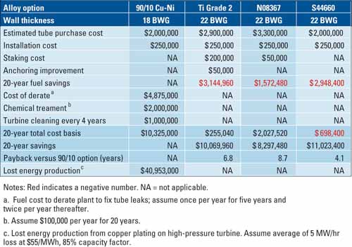
Table 2. Installation and operating costs of various tube candidates for a 300-MW power plant condenser estimated over a 20-year operating life. Source: Plymouth Tube
At this point, we must include an estimate for operation and maintenance costs for the various tube candidates. Based upon the fuel costs that we calculated in Table 1, we expect a savings of $3.1 million over 20 years for titanium, $1.55 million for N08367, and almost $3.0 million for S44660, compared with 18 BWG copper nickel. Our experience with the copper nickel tube is that we will get occasional tube leaks, predominately from erosion/corrosion from entrapped debris. We estimate that this will occur once per year during the first five years and twice per year after five years. Fortunately, this condenser is of a divided flow configuration, so we do not need to completely shut the plant down to fix the leak. To locate the leaks and plug the tubes, it normally takes us two days. During a derate of that timeframe, we typically lose $225,000 of income. As the other tube candidates are not susceptible to erosion corrosion, no cost was assigned.
Our traditional cost for chemical treatment (pH adjustment, ferrous sulfate treatments, and others) to protect the copper tubing has been about $100,000 per year. These will not be required, or will be minimal, with the other alternatives.
It’s common to see a significant drop in plant output due to copper build-up on the high-pressure (HP) turbine blades. Copper deposits build up on HP turbine blades, lowering the efficiency of the turbine and restricting the overall plant output. Approximately every four to five years, the derate is significant enough to justify cleaning the turbine at a cost of approximately $250,000. As all of the copper-based feedwater heaters have been replaced with other alloys in this case study, the only remaining source for copper is the condenser. If we choose titanium or the high-performance stainless steels, this cleaning cost disappears.
Summing of the installation, operation, and maintenance cost components, but not including the base 90-10 related fuel cost, we see some very significant cost differences between the condenser tube candidates. The combination of the derate costs required to fix tube leaks, water chemistry control, and additional cleaning required due to copper transport adds over $10,000,000 to the cost directly related to using copper-nickel condenser tubing. Although the installation and tubing costs of the titanium and N08367 options are significantly higher, this is mitigated by a significant fuel saving (compared to the Cu-Ni option) for titanium and, to a lesser extent, for N08367. The 20-year fuel savings pays for approximately 92% of the titanium installation costs and about 44% of the N08367 costs.
Copper-Free Turbine Drive Economics
One very significant performance penalty was not included in the 20-year analysis. In the last row of Table 2, copper deposits on the HP turbine blades can have an enormous financial impact. Derates of 20 MW or greater are possible on a plant of this size after a four- or five-year period and must be accounted for in the economics of tube replacement. Consider the following assumptions:
- The turbine is cleaned every four to five years.
- The average MW derate is 5 MW.
- The plant is in operation 85% of the time.
- The average selling price is $55 per MWh.
In this situation, the total income lost over the 20-year period is more than $40 million dollars and completely overpowers the economic analysis factors. This result emphasizes how important it is to keep the plant operating efficiently and the importance of keeping the turbine free from copper deposits in particular.
—Daniel S. Janikowski ([email protected]) is group leader, power generation for Plymouth Tube.