Combined Cycle Users’ Group completes another successful year

The third annual meeting of the Combined Cycle Users’ Group (CCUG) was held May 2–4 in Atlanta at Electric Power 2006, in cooperation with the ASME Power Division Combined Cycles Committee and other industry groups. The CCUG’s leadership (Figure 1) drives the group to address issues involving the major components of a combined-cycle plant and their interactions, which are many. With gas prices now dipping below double digits, such issues have never been more important to owners and operators of plants that are now operating on the razor’s edge of profitability and in modes for which they were not designed.
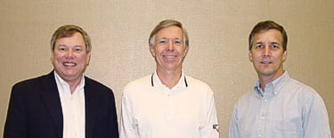
1. CCUG leadership. Andrew Donaldson of WorleyParsons, chairman of the CCUG, is flanked on the left by Jeff Schroeter of Genovation Group and on the right by Steven Clark of WorleyParsons. Source: POWER magazine
Presentations at the meeting touched on a wide variety of topics. Among the more eclectic was repowering combined-cycle (CC) plants to burn gasified coal. Among the more mundane were selective catalytic reduction (SCR) system maintenance, the effects of cycling heat-recovery steam generators (HRSGs), staff training, and adopting best practices in O&M. Judging from the lively discussions and questions following the presentations (Figure 2), it was clear that operating a power plant is still as much art as science.
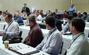
2. Fire away. Presentations and panel discussions were followed by questions from the floor, where personal experiences could be shared among peers. Source: POWER magazine
Retrofitting CC plants for syngas
Kajal Mukherjee of WorleyParsons (Figure 3) got the ball rolling with a thought-provoking discussion of the technical requirements for “refueling” an existing CC plant with synthetic gas, or syngas. The consensus among most participants before the meeting was that such refueling is both on the horizon and not particularly challenging. But preconceived notions have a way of evaporating when their holders are faced with the cold facts. The technical challenges inherent in adapting a CC plant to burn syngas are no different.
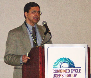
3. Tough, but doable. Kajal Mukherjee of WorleyParsons explains the technical difficulties of retrofitting an existing combined-cycle plant to burn syngas. Source: POWER magazine
Part of Mukherjee’s presentation focused on practical issues, such as shoehorning the vessels and support equipment for the gasification plant into an already cramped site. He also addressed the need to closely consider fuel supply, transportation, storage, and handling concerns if the gasifier is to be placed close to the CC plant. For many smaller CC plants, repowering would be unfeasible if the added gasification plant and its infrastructure end up larger than the power block. Mukherjee also touched on other salient repowering issues, including the need to handle and dispose of waste by-products, which would require a plant to obtain new environmental permits.
According to Mukherjee, if the syngas plant is located elsewhere and the gas is made available locally, the challenges of retrofitting existing equipment still remain. For example, the mass flow of the low-Btu syngas (approximately 300 Btu/scf for an air-blown gasifier) will be substantially greater than that of natural gas. Accordingly, piping, compression requirements, and combustor design issues become paramount, necessitating significant changes and modifications.
Although the additional mass flow may result in a 15% to 20% increase in power output (if the plant’s generator and switchgear are up to the task), the downside is that the HRSG may be unable to handle the increased mass flow unless it was designed to be highly fired in the first place. What’s more, the higher mass flows and the exhaust constituents will almost certainly wreak havoc with the long-term performance of an existing SCR and/or CO catalyst. Additional surface area in the HRSG, an economizer bypass to prevent steaming, and the ability to handle increased metal temperatures to obtain acceptable thermal performance also will be required. Finally, Mukherjee asked, what do you do with all that extra steam you’ll generate? Because the plant’s steam turbine-generator typically will be too small to convert it to electricity, much of the steam will end up in perpetual bypass unless other uses for it are found.
The trickle-down problems resulting from having significantly more exhaust mass flow than the original design makes refueling an existing CC plant even less palatable. For example, changes to steam piping and the ammonia injection grid likely will be necessary. Because more steam flow implies higher water flows, the plant’s makeup system and polishing system, pumps, valves, and the like may prove to be undersized. At the end of the day, repowering a CC plant could be much like renovating an old house: Lurking behind every wall are new “opportunities” to repair and replace equipment at considerable cost. Refueling opportunities may turn out to be limited when the economics are closely examined.
Turbines: Already syngas-ready
Don Fraser of Siemens Power Generation acknowledged that repowering a CC plant is no walk in the park. But he also noted that today’s combustion turbines are much more flexible with respect to fuel composition than they were and that their hardware can process syngas with a dry NOx level of around 15 ppm.
That fuel flexibility is a function of combustor design, Fraser explained. Although premixed combustors are used on the newest DLN (dry low NOx) and DLE (dry low emissions) engines introduced in the 1990s, the diffusion combustor still is preferred for low-quality gaseous or liquid fuels. Low-quality fuels are normally defined as landfill gases, heavy- and medium-grade oils, residual fuel oil, blast furnace gas, refinery gas, and the syngas output of a coal gasification plant.
The Siemens approach to handling these alternative fuels is to use a proven syngas combustor for turbines, such as the SGT6-5000F. This dual-fuel (syngas or natural gas) combustor can burn a wide range of syngases and can switch between fuels while the turbine remains on-line. Syngas fuel supply/purge skid, diluent (N2 or steam) injection skid and manifolds, extraction air skid and manifolds, and upgraded control and electrical protection modifications round out the top-level changes required. However, the size of the overall package may have to be increased to handle the larger fuel supply piping surrounding the combustor section.
To wrap up his presentation, Fraser presented some figures showing that, for 60-Hz applications, the performance of syngas-capable gas turbines compares very favorably to that of natural gas–fired units at ISO conditions (see table).

Comparing the performance of turbines burning syngas and natural gas Source: Siemens Power Generation
Racing toward the future
Dr. Susumu (Sam) Sato (Figure 4), senior engineering advisor for Mitsubishi Power Systems (MPS), highlighted the development history and aggressive R&D work under way to bring the company’s integrated gasification combined-cycle (IGCC) plant to market. The plant uses an air-blown gasifier with a membrane waterwall. Coal is added to the lower combustor section, which burns the fuel substoichiometrically. The gas produced enters the top section of the gasifier (or redactor), whose product (consisting of CO and H2) is cooled in the endothermic second stage. Char and slag are removed from the bottom of the vessel.
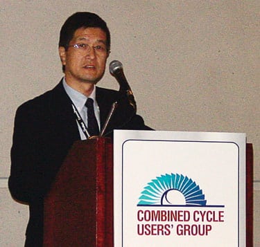
4. Pioneering plants. Dr. Susumu (Sam) Sato of Mitsubishi Power Systems describes his company’s experience with a pilot integrated gasification combined-cycle (IGCC) plant and with the construction of a half-size commercial IGCC plant now under way in Japan. Source: POWER magazine
Lest you think this is just another R&D design looking for a home, consider the development plant experience that MPS has tucked under its belt since the early 1980s. Without going into the details of the design’s pedigree, there are a couple of important engineering milestones worthy of note. First is the 200 ton/day pilot plant (with a 12.5-MW gas turbine, but no steam turbine) built at the Nakoso Power Plant of Joban Joint Power Co., Ltd., in Iwaki City, Fukushima. The testing was sponsored by nine power companies; Electric Power Development Co., Ltd.; and the Central Research Institute of Japan’s electric power industry. To prove the design, the plant was tested for almost 5,000 hours, which included a 789-hour continuous run.
The results of the pilot plant testing were rolled up into the design of a 250-MW IGCC demonstration plant burning about 1,700 tons/day of syngas (roughly a half-size commercial plant). One of the key objectives of the demonstration project is to match the net efficiency of Japan’s latest ultra-supercritical steam plants, and in this respect the project seems to be on track. Although the demo plant uses D-class gas turbines, the commercial plant envisioned will use G-class technology that will raise its rating to around 650 MW and its efficiency to nearly 50%.
The gasifier that MPS chose is a Nakoso two-stage, dry feed, air-blown, entrained-flow unit. Complementing it is a modified M701D gas turbine (with a 2,200F inlet temperature and rated at 142 MW under ISO conditions) with air extraction for the gasifier. A booster compressor for the extracted air is required to match the increased pressure drop of the gasifier system. The demo project’s steam turbine is rated at 110 MW, which seems a bit much until you consider the volume of steam that the gasifier also generates. The target efficiencies of the plant are 48% (gross) and 42% (net), based on coal’s lower heating value. Emissions are expected to be 8 ppm of SOx after wet chemical absorption for sulfur removal and 5 ppm of NOx with an SCR system. Kerosene is the combustion turbine’s start-up fuel.
The demonstration test is to be conducted by Clean Coal Power R&D Co. Some 30% of the project’s cost is being paid for by Japan’s Ministry of Economy, Trade, and Industry; the remainder is being shared by a consortium of 11 corporations, nine power companies, Electric Power Development Co., and the Central Research Institute. The demonstration plant, which is now under construction, is expected to begin operational testing in late 2007.
Clean up that gas
It’s difficult to remember when an SCR system wasn’t required on a new combined-cycle plant; the industry pretty much takes them for granted these days. Cormetech’s Elizabeth Govey (Figure 5), manager of sales engineering, gave an excellent presentation on state-of-the-art SCR design that proves that not all SCRs are created equal.

5. Easy being green. Elizabeth Govey describes Cormetech’s Zero Slip catalyst project and suggests ways for selective catalytic reduction users to improve their O&M practices. Source: POWER magazine
Two environmental metrics that seem to reflect the vagaries of local regulators are a plant’s outlet NOx level and its NH3 slip specifications. Over the past few years, the constraints on some CC projects—such as the Boston Mystic and Fore River Stations (POWER, November/December 2005) were ratcheted down to 2% ammonia slip and 2 ppm of NOx at the stack. Considering that Mitsubishi Heavy Industries’ 501G has about 50 ppm in its exhaust, these numbers suggest a need to improve NOx-reduction efficiency by 96%. Most other locales seem to have settled at 5% slip, which seems a bit more realistic.
Of course, the optimum (from a regulator’s point of view) would be a plant with zero slip. A Solar Turbines Inc. 7-MW gas turbine is at the heart of a commercial demonstration plant that demonstrates Cormetech’s Zero-Slip technology. At the plant, which was built at Paramount Petroleum Corp. in the Los Angeles basin and started up in February 2003, the SCR system is followed by the precious-metal Zero-Slip catalyst and CO catalyst. To date, the plant has met its performance goals of <0.1 ppm NH3 slip and <1 ppm NOx. Long-term monitoring of the plant continues.
A number of comments during the Q&A session following Govey’s presentation were very illuminating. One attendee mentioned that the catalysts of SCR systems used with gas turbines lose porosity over time because they are not regenerated and reused, as SCR catalysts used in coal-fired power plants are. For this reason, in some cases it’s more cost-effective to add a second layer of catalyst if ammonia use rises to some predefined level than to replace the entire original catalyst—that is, if you have enough pressure-drop margin and room to do so.
Ways to extend catalyst life also were discussed. Based on Cormetech’s experience, it’s wise to carefully inspect the HRSG ductwork to locate any possible gas path leak that would allow exhaust gases to bypass the catalyst section, because such leaks could increase ammonia consumption. Furthermore, CO catalysts have been known to cause flow distribution problems across a downstream SCR, with the same result. Correcting these problems will not only extend catalyst life but will reduce ammonia consumption and slip as well.
Another attendee suggested that annual tuning of the ammonia injection grid is a sound operating practice. It would consist of doing a NOx traverse, followed by making the appropriate adjustments on the individual gate valves on the injection grid and then locking them. Using more than the necessary amount of NH3 doesn’t necessarily degrade the catalyst, but it does run up your operating costs.