CO2 Blasting Restores HRSG Performance
Steam production is strongly influenced by the cleanliness of the gas-side heat transfer surface in a heat recovery steam generator (HRSG). However, when deposits begin to impede heat transfer or increase gas-side pressure drop, it is time for a cleaning. CO2 pellet blasting is a cost-effective and environmentally benign cleaning method available to power plant owners and operators.
Every heat recovery steam generator (HRSG) will eventually experience fouling caused by tube deposits and corrosion that will reduce steam production, decrease steam temperatures, and thus degrade combustion turbine (CT) and combined cycle performance. These performance losses hit the plant’s operating economics in the form of increased fuel consumption and lost electricity sale revenue, not to mention other economic losses that result from an extended plant outage for cleaning the HRSG.
Fouling of HRSG tubes is often caused by fuel sulfur content, tube leaks, ammonia injection for NOx control, and condensation due to low stack temperatures. Fouling also is often found in plants operating in locations with high humidity, particularly with cycling plants originally designed for baseload operation.
Fouling of the finned tubes in an HRSG occurs when, over time, deposits “bridge” the gap between adjacent tube fins or other heat transfer surfaces, further disrupting heat transfer and increasing the gas-side pressure drop. Increased HRSG gas-side pressure drop subsequently degrades CT power production, increases CT heat rate, and thus lowers the efficiency of the entire combined cycle plant. In cases where HRSG performance is severely compromised, the entire plant may require an extended forced outage to repair corrosion-induced tube leaks, clean tubes of deposits, or even replace an entire module (Figure 1).
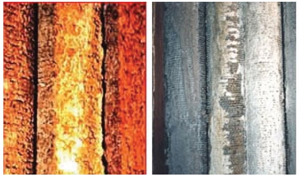 |
| 1. Fouled tubes. Typical examples of the fouling often found on heat recovery steam generator (HRSG) tube modules. Courtesy: Environmental Alternatives Inc. |
Remove Deposits and Corrosion
Every plant’s annual maintenance program should include removal of HRSG gas-side deposits. Effective maintenance planning can be improved by closely monitoring specific operating parameters, such as CT backpressure, steam production and temperature (for each pressure level), and stack temperature, and comparing the data against corrected plant design conditions. In addition, plant heat rate and output should also be tracked.
Consider preparing a separate screen on your distributed control system that displays performance data that will provide advance warning about the location of tube fouling, the amount of fouling present, and the rate of deposit formation within the HRSG. This data will allow you to schedule an HRSG cleaning outage based on predetermined plant operating economics rather than as an emergency evolution; this approach often means that cleaning can be added to a future planned outage. In general, HRSG cleaning is required when the gas path pressure drop across the HRSG reaches 3 to 4 inches H2O over “new and clean” condition.
Once the need for cleaning has been established and an outage date determined, the next step is selecting the best available cleaning technology. The standard options for cleaning an HRSG are high-pressure water blasting, grit blasting, and carbon dioxide (CO2) blast cleaning. The plant owner should carefully consider the pros and cons associated with each cleaning option before making a final selection.
High-Pressure Water Blasting. High-pressure water blasting can be effective but may have the undesirable side effect of a water-deposit interaction that accelerates tube corrosion or may turn the water-deposit mixture into a concrete-like substance. Also, this form of cleaning is limited to line-of-sight deposits, and the high-pressure water may push removed deposits further back into inaccessible regions of the HRSG. Unless carefully performed, high-pressure water blasting can also quickly damage insulation that is extremely difficult to access for repairs or may erode some tubes or damage tube fins. Contaminated water from the blasting is also difficult to contain and may require expensive waste disposal, if it is determined to be a hazardous waste.
Grit Blasting. Grit blasting, also limited to line-of-sight cleaning, can quickly thin the metal tubes or damage tube fins if not carefully performed by experienced technicians. Unfortunately for the plant owner, thinning of tube walls is not obvious during cleaning but will become apparent when the rate of tube leaks increases in the future. As with high-pressure water blasting, large amounts of waste material are generated, some of which may be classified as a hazardous waste requiring special (and expensive) handling and disposal.
CO2 Blast Cleaning. The favored approach for HRSG cleaning is CO2 pellet blasting, the only option that is nondestructive and produces no secondary waste products. CO2 blasting is a dry process that avoids future heat transfer surface corrosion and eliminates the risk of erosion of tube metal surfaces. Just as important to the owner, deep cleaning between tubes can be performed. CO2 blasting penetrates and completely cleans modules located deep within the HRSG, eliminating the time and expense of mechanically spreading tubes to obtain access to tubes not within the technician’s line-of-sight.
CO2 Blasting Details
CO2 blasting has been proven by over 20 years of industry experience and has been recognized by HRSG manufacturers as a cleaning best practice (Figure 2). Returning the HRSG to a clean condition restores lost steam production, which in turn increases overall unit performance and efficiency.
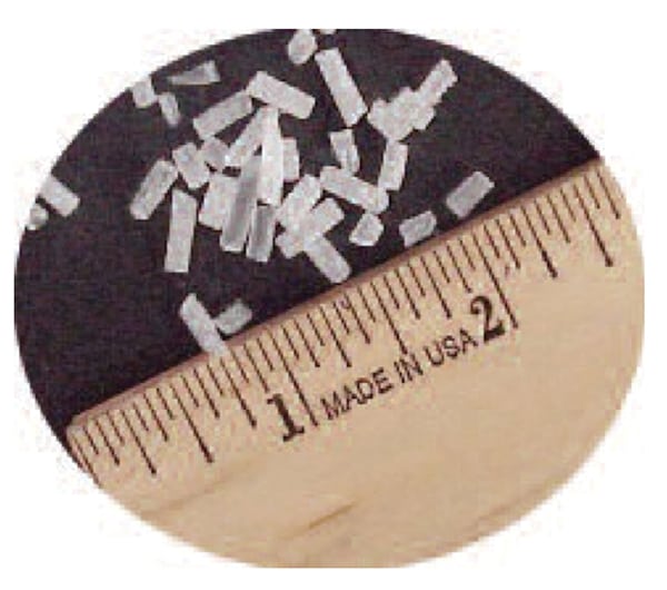 |
| 2. Miniature pellets. CO2 blast cleaning uses small cylindrical dry ice pellets to remove fouling, rust, and scale from tube and fin surfaces. The process involves conversion of liquid CO2 to solid dry ice pellets. Cylindrical dry ice pellets used in CO2 blasting are approximately ¼ inch across. Source: Environmental Alternatives Inc. |
The general cleaning process is illustrated in Figure 3. CO2 pellets are fed into a portable machine that is connected to a high-pressure compressor. The pellets are educed into the air stream and propelled through a hose to a specially designed nozzle that propels the pellets at speeds up to 1,000 feet/second. The pellets exit the nozzle and penetrate the debris layer on the surface being cleaned (Figure 4).
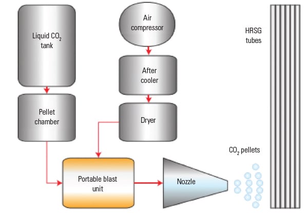 |
| 3. A blast of cleaner. This diagram depicts the CO2 pellet blast cleaning process. Source: Environmental Alternatives Inc. |
 |
| 4. Sharpshooter. A nozzle directs the pellets directly on deposits. When the CO2 pellets change phase, the deposit breaks free. Courtesy: Environmental Alternatives Inc. |
The CO2 pellets sublimate once the deposit is penetrated. During sublimation at atmospheric conditions, the CO2 pellets undergo a transformation from a solid directly to a gas, unlike ice that must first melt into liquid water before evaporating into vapor form. When CO2 sublimates from a solid to a vapor, it expands 750 times in volume creating a “mushroom” effect inside the deposit that lifts and removes deposits from metal surfaces. A HEPA vacuum system is then used to collect the deposits removed from the boiler tube surface that just fall onto the floor.
High-density CO2 pellet production is the cornerstone of the cleaning process. Sufficient pellets are manufactured onsite to guarantee the quality and density for maximum cleaning effectiveness.
On-site production of CO2 pellets is possible by using a completely self-contained mobile support trailer. The trailer houses a high-end, high-pressure compressor, air dryer/after-cooler (for clean instrument-grade air with low moisture content), a liquid CO2 storage tank, a pellet conversion unit, and all necessary support systems for direct connection to site power. The trailer also carries all the necessary tools, personal protection equipment, and other safety gear to the site. Pre-made pellets from offsite dry ice vendors are usually 24 to 48 hours old before they are used, and the pellets will have already experienced a loss in density. Lower-density pellets will begin to sublimate in the hose and will have reduced clearing efficiency.
Two Case Studies
The true effectiveness of CO2 blast cleaning becomes evident when comparing pre- and post-cleaning plant performance data. In the first case study, a significant level of performance was restored after cleaning. In the second case study, the value of a CO2 blast cleaning allowed the owner to cancel a scheduled major outage and avoid paying for a replacement economizer module.
Case Study 1: Restoring Lost Performance. PurEnergy is the asset manager and operator of Maxim Power Corp.’s Pittsfield Generating Plant, located in Pittsfield, Mass. The 170-MW merchant power station consists of three 42-MW General Electric (GE) Frame 6B dual-fuel CTs, each exhausting into a Deltak HRSG that produces steam for a single 55-MW GE steam turbine. The CTs use steam injection for emissions control. The plant entered commercial service in 1990 and sells its power into the ISO-New England market.
Increased HRSG pressure drop caused by accumulated fouling, insulation, dust, and scale on the tube surface led PurEnergy to schedule Environmental Alternatives Inc. (EAI) to clean the 10 tube bundles (20 tube surfaces) plus the selective catalytic reduction system within the Unit B HRSG. EAI was selected because the company has successfully cleaned HRSGs at other PurEnergy sites in past years, including at Pittsfield. The cleaning was scheduled to take approximately 168 hours (two 12-hour shifts over seven days) during a pre-scheduled April 2014 outage.
Data collected from the plant’s PI data historian showed that Unit B operated with an average HRSG backpressure of ~19.5 in. H2O at full CT load prior to cleaning. Post-cleaning data showed the full-load HRSG pressure drop was reduced to ~13.2 in. H2O, a reduction of 6.3 in. H2O. Economic savings resulted from the cleaning due to improved CT heat rate and thermal efficiency.
A rough estimate of the fuel savings that result from improved heat rate can be derived using the exhaust pressure correction factors for the Frame 6B found in GE Power Systems Bulletin GER-3567H. That publication states that exhaust loss of 4 in. H2O translates into a 0.42% power loss and a 0.42% increased heat rate; therefore, 6.3 in. H2O pressure drop is equivalent to a 0.66% change in power and heat rate.
In this example, a reasonable estimate of the CT heat rate at standard conditions is ~9,500 Btu/kWh, so the fouled HRSG increased the CT heat rate by ~63 Btu/kWh at a nominal average load of 40 MW. If a plant is operating at 70% capacity factor, using an average price of $4/million Btu fuel, the increased heat rate added ~$62,000 to the plant’s fuel bill, assuming the HRSG remains clean for the entire year. A better prediction assumes that the HRSG will gradually return to its pre-clean condition during the following 12 months, so the annual heat rate savings is linearly interpolated as $30,000.
The power loss equates to ~0.24 MW, which represents ~$75,000 in lost power sales during the year, if power is sold at $50/MWh.
In summary, the annualized value of this clean HRSG is estimated as ~$105,000 per year in avoided lost energy sales and increased CT fuel consumption. In this example, the cost of the HRSG cleaning would be recouped in a month or two.
Case Study 2: Avoiding Expensive Upgrades. A combined cycle cogeneration plant located in the United Kingdom (UK) produces steam and electricity for two paperboard mills. The plant uses a GE LM6000 and a Siemens steam turbine. Sticky combustion products were condensing out on the HRSG economizer tubes as a tar-like substance due to the flue gas temperatures dipping below the dew point. In addition, ceramic fiber insulation blocks used in the HRSG combustion zone were deteriorating, with fiber strands coming loose into the gas flow and sticking on the economizer fin tubes. The combined effect was a loss of heat transfer in the economizer and a rise in the HRSG gas-side pressure drop that severely decreased steam production.
The plant owner’s initially considered option was to replace the entire economizer module with one that is equipped with an economizer recirculation system. An economizer recirculation system takes a portion of the hotter economizer outlet water and returns it to the inlet to ensure the economizer tube metal temperature remains above the dew point temperature, thereby avoiding condensation of sticky combustion products. However, procuring an expensive new economizer module was going to require at least 40 days, which would put the plant owners at commercial risk for failing to supply the contracted amount of steam.
As an alternative approach, the plant owner investigated cryogenic cleaning of the economizer, even though at the time there was no large boiler experience with the technology in the UK—only cleaning of small equipment, such as motors or generator windings. The plant owner sent representatives to the U.S. to observe the cleaning process in action, and the decision was made to bring the process to the UK for the first time. The CO2 pellet blasting equipment was shipped to the UK for a planned HRSG outage. Figures 5 and 6 show the state of economizer tube fowling before and after cleaning. Figure 7 shows the debris removed from the HRSG after the cleaning was completed.
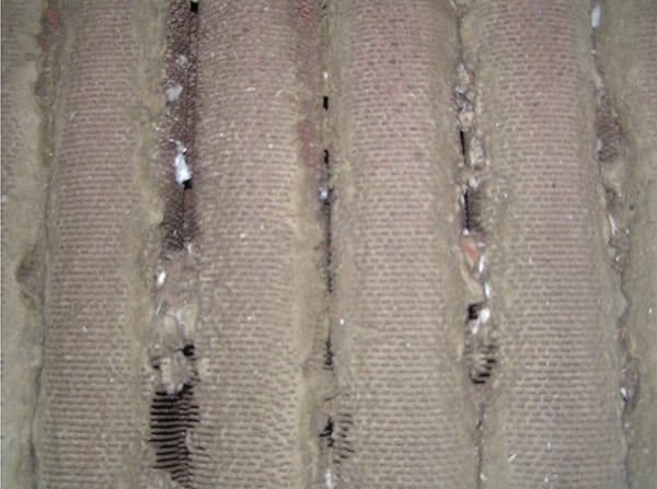 |
| 5. Pressure reduction. Fouling in this economizer was reducing the customer’s process steam flow and increasing HRSG pressure drop to unacceptable levels. A replacement economizer was thought to be the only solution. Courtesy: Environmental Alternatives Inc. |
 |
| 6. Squeaky clean. Economizer fouling was eliminated during a short maintenance outage, and the plant was quickly able to resume full process steam supply to its customer. In addition, the reduced gas side pressure drop improved the combustion turbine operating efficiency. Courtesy: Environmental Alternatives Inc. |
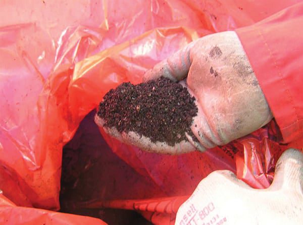 |
| 7. Easy disposal. The sticky material on the economizer was reduced to an easily handled and disposed of waste product. Courtesy: Environmental Alternatives Inc. |
The cleaning process was very successful, and at the close of the outage, the plant resumed supply of the contracted amounts of steam to the customer. By selecting CO2 pellet cleaning, the plant owner avoided an unnecessary replacement economizer expense and sidestepped an extended outage for the economizer replacement. ■
— Chris Norton ([email protected]) is president of Environmental Alternatives Inc. Rich Taikowski Jr. ([email protected]) is plant manager of PurEnergy Operating Services LLC.