Blades, better than new
Most combustion turbine owners and operators hope that replacement parts will simply duplicate the performance and reliability of the original. That’s not good enough for Eastern Technical Services (www.etspower.com), which combines new technology with industry experience in its efforts to provide better and cheaper alternatives.
ETS was founded in Stuart, Fla., in 2000 by former engineers and executives of the gas turbine original equipment manufacturer (OEM) Pratt & Whitney. The company’s biggest customers are turbine users who rely on ETS for manufactured parts, custom design and inspection services, and product life-cycle management.
A key advantage of buying aftermarket parts is knowing that they incorporate the latest in advanced materials and protective coatings and were designed using precision, state-of-the-art methods. By contrast, an OEM part may not have been upgraded in a decade and has probably been sitting in a warehouse somewhere for just as long.
Do you operate one or more gas turbines that might benefit from a fresh set of buckets or nozzles, upgraded combustion liners and transition pieces, or new fuel nozzles? A few phone calls to the OEM about replacement parts may have given you sticker shock and convinced you that your budget can’t cover them. At this point, aftermarket parts may look pretty good. But they’ll look even better when you realize how precisely turbine blades are recreated, making them distinct improvements over the originals.
Turbocharged tool
Over the past few years, ETS has leveraged its engineering expertise with digital shape sampling and processing (DSSP) technologies to fuel major leaps in design productivity.
DSSP is a category of tools that encompasses multiple technologies. It enables engineers to use scanning hardware and geometry processing software to represent physical objects in digital form. By crunching data in the digital domain, DSSP can automatically create accurate 3D models of real-world structures to facilitate their design, engineering, inspection, testing, and manufacturing. What digital signal processing is to audio, DSSP is to 3D geometry.
DSSP requires two essential components: an optical scanner to capture point data and software to convert the data to binary form. The advances in scanner technology made over the past decade made DSSP possible. Previously, engineers were limited to manually capturing one point at a time. Modern optical scanners can collect millions of points in the time it used to take to record a few points. With DSSP, it is possible to capture the entire bounding surface geometry of a physical object, including its features, colors, and even textures.
Gathering millions of points of data would have little or no value, of course, unless the data could be assembled into models precise enough for design, analysis, prototyping, or manufacturing work. That’s where software plays a critical role.
Ever-more-affordable desktop processing power and the advent of innovative geometric processing algorithms have made DSSP a mainstream application. Point-cloud data that would have choked a high-end computing system five years ago now can be easily digested by a modern PC. Gaps and noise in scanning data that used to take days to resolve are now corrected automatically. Conversion to polygons and non-uniform rational b-spline (NURBS) surfaces, which once required days of tedious work, now can be handled in minutes using a natural, intuitive workflow.
From scan to CAD drawing
Between 2000 and mid-2004, ETS digitally recreated about 10 to 12 airfoils a year. In the two years since it began using both ATOS scanners from Capture3D (www.capture3D.com) and a software suite from Geomagic Inc. (www.geomagic.com), the company has completed as many as 120 digital reconstruction and inspection projects, according to Scott T. McAfee, senior technical leader for reverse engineering.
Beyond speed, ETS has benefited from a new level of control that McAfee relates directly to quality. "We can now do everything—from digital reconstruction to inspection and trend analysis—in-house, which not only saves time but ensures quality and consistency," he explains. "The same person who scans the part can process the data sets in Geomagic Studio. With Geomagic Qualify, we can do everything ourselves to ensure that the model represents the ideal physical part."
The process starts with several samples of the part that ETS has been contracted to digitally reconstruct. The samples provide just enough information to quantify differences, but not so much that scanning and geometry processing become too time-consuming.
Sample parts are captured digitally by the ATOS scanner, which uses a white-light projection unit to beam patterns onto the part’s surface. The pattern is captured with two integrated cameras at either side of the scanner’s sensor head. The ATOS software can calculate the precise 3D coordinates of up to 4 million object points in seconds (Figure 1). Figures 2 through 8 illustrate the remainder of the blade design sequence.
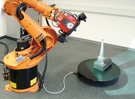
1. Parts into points. A turbine blad is captured by an ATOS white-light scanner from Capture3D. Courtesy: ETS Power Group

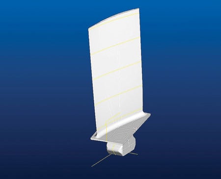
2. Average data set with sections. Object averaging in Geomagic Studio creates a single STL file that represents an average part, based on multiple scans. Courtesy: ETS Power Group

3. CAD model with sections Geomagic. The CAD model sliced into cross sections using Geomagic Studio. Courtesy: ETS Power Group
4. CAD model and sections CAD. A turbine blade CAD model derived through hybrid modeling using Geomagic Studio and CAD software. Courtesy: ETS Power Group
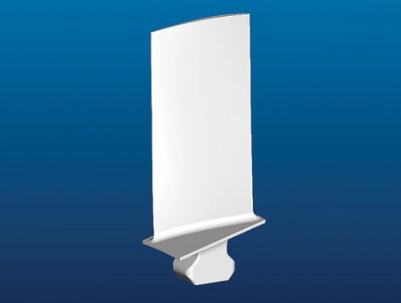
5. CAD model in CAD. The completed CAD model produced using hybrid modeling. Courtesy: ETS Power Group
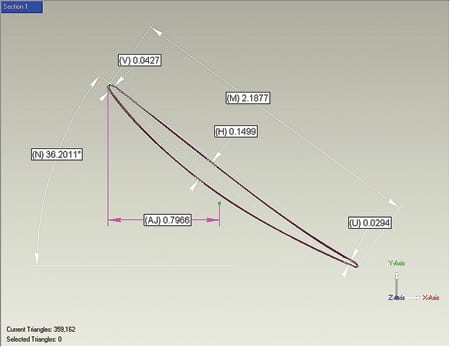
6. Airfoil section data in Geomagic. ETS uses Geomagic Blade software to extract features and characteristics for cross sections of the turbine blade. Courtesy: ETS Power Group

7. Layout sketch in CAD. A CAD drawing of the turbine blade layout derived from Geomagic Blade and Quality. Courtesy: ETS Power Group
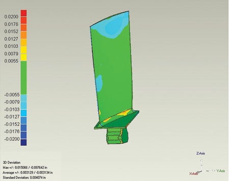
8. Comparison of CAD and average. This comparison was made in Geomagic Qualify of the averaged model derived from scan data and the CAD model. Courtesy: ETS Power Group
Files from the ATOS software, in the Standard Tessellation Language (STL) file format, are imported into Geomagic Studio, which automatically registers the various scans into alignment, saving considerable time over trial and error methods. Color maps graphically show any alignment problems for each scan, making it simple to identify deviations. "The automatic aligning of the datasets makes life much easier," says McAfee, "and it doesn’t require any special skills."
With minimal training, ETS engineers have been able to become adept with Geomagic Studio in about a month, according to McAfee. Learning Geomagic Qualify usually takes a bit longer because of the depth of functionality that ETS wanted to put to daily use.
Once the datasets are aligned in Geomagic Studio, ETS uses the software’s automated tools to repair the STL data, cleaning the mesh and filling holes. Cleanup is followed by the key step of object averaging, which throws out anomalies and gives ETS a single STL file that represents an average part.
If the part being reconstructed is an airfoil, engineers then use Geomagic Studio to calculate the stacking axis of the blade. That’s followed by a command that aligns the part to the world coordinate system used for the rest of the engine.
Perfectly parametric
The next step is a process called "hybrid modeling." It combines the distinctive features of Geomagic and computer-aided design (CAD) software into a parametric model.
Traditional CAD models are created by defining a construction sequence of 2D and 3D entities (features). Using a process called prescriptive modeling, CAD software users create new designs by specifying the parameters of these entities to control the shape of the object they are modeling.
Although this traditional CAD approach is good when modeling from scratch, it has shortcomings when reconstructing a complex surface: It takes a lot of time and effort, and there are no guarantees that the model will be accurate. In some cases, it is almost impossible to use a feature-based approach to reconstruct surfaces, due to the difficulty of identifying and quantifying the parameters that control the object’s shape.
Hybrid modeling provides a solution to the shortcomings of traditional CAD for reconstructing complex surfaces. Basic reference geometry—such as a reference datum, curves, and primitive features—can be measured and extracted from the 3D scan data. Data can be moved easily between the CAD program and Geomagic Studio, leveraging what each program does best.
ETS uses the hybrid process to slice the digital model into cross sections within Geomagic Studio and export it as an Initial Graphics Exchange Specification (IGES) file into CAD software, where curves are lofted to create parametric surfaces and solids.
The parametric model is then exported as an IGES file into Geomagic Qualify, where the CAD-derived surfaces are compared with scan data from the averaged physical part. Based on the results, curves are modified in CAD, resurfaced, and checked again. This process is repeated until the CAD model and the scan data match within a specified tolerance.
Once the CAD model is finalized, ETS uses Geomagic Qualify and Geomagic Blade—a specialized application for turbine blade inspection—to determine dimensions. Geomagic Blade extracts specific features and characteristics of the blade—such as its leading-edge radius, maximum thickness, and chord length—to create cross sections of it. Geometric Qualify then takes that information and provides dimensions, which are used to populate the CAD drawing. The result is a fully dimensioned parametric part that is ready for an initial manufacturing run.
Trendspotting
After a short manufacturing run, ETS uses Geomagic Qualify to conduct detailed first-article layout inspection and a trend analysis on a 10% sample of parts. Qualify can batch-process 10 or more scans at a time. Results are reported within a customized Microsoft Word template that ETS created within Qualify. Qualify takes the results and automatically compiles statistics on 40 or more reports at a time, documenting the trends within an Excel template. Free Geomagic Review software is used to share trends internally and with customers without tying up a Studio or Qualify license.
As part of its inspection and quality-control processes, ETS has brought troubleshooting into the mix. In one instance, a customer asked ETS to investigate a problem with a turbine blade that contained too much twist, the result of the wax pattern deforming during the solidification process prior to mold preparation. ETS used the 2D twist analysis feature of Geomagic Blade to determine the twist and displacement at various sections and then calculated the amount of force required to clamp the wax pattern and prevent it from deforming.
New data extraction and trend analysis capabilities also play key roles in many ETS projects. "Our ability to inspect parts and conduct trend analysis through reports enables us to certify repairs, assess PMA [parts manufacturing authority] compliance, and ensure quality by adhering to a tolerance range over a representative sampling of parts," explains McAfee.
In the past, data extraction and trend analysis required taking individual sections from each sample, laying them out in 2D, compiling dimensions in a spreadsheet, and then doing a manual search for trends—a process that took weeks. With the ATOS scanner and Geomagic Qualify software, a much greater sampling can be handled automatically in days.
Beyond reverse engineering
DSSP and the expertise of ETS in applying it go well beyond the typical definition of reverse engineering. The company can do much more than manufacture clones of an OEM part. It can also improve a part’s specs, remove manufacturing anomalies, ensure consistency from part to part, and experiment with design changes that may improve performance in the future.
"There’s a lot more to it than just replicating a part," says McAfee. "We’re infusing the part with much greater information. [The process] now has data associated with it that can be used for continuous improvement throughout a part’s life cycle."
—Bob Cramblitt is principal of Cramblitt & Company, a communications company based in Cary, N.C. He can be reached at [email protected].