Benefits of evaporating FGD purge water
In coal-fired power stations, flue gas desulfurization (FGD) is used to “scrub” most of the sulfur dioxide (SO2) from the gas. FGD is often performed using a wet process in which SO2 is absorbed from the flue gas by spraying it with a slurry containing limestone (mainly calcium carbonate, CaCO3). The SO2 reacts to form calcium sulfite, CaSO3, which is further oxidized to produce gypsum (CaSO4 x 2H2O) by introducing air into the scrubber. The gypsum product is often washed and sold for various uses; otherwise, it is disposed of in a landfill.
Scrubber wastewater chemistry
Water uses in a limestone-gypsum FGD scrubber are easily identified (Figure 1). The gypsum has to be removed continuously from the scrubber, and it is replaced by fresh limestone. In addition, a certain proportion of the circulating water is removed as effluent to control the buildup of chloride from coal combustion products in the scrubber water. The circulating scrubber water also contains other water-soluble impurities from the flue gas and the limestone.
1. Water lines. This diagram shows the inputs and outputs of a typical limestone-gypsum wet scrubbing process. Source: HPD
FGD is an evaporative process, so it concentrates these impurities. The wastewater from gypsum dewatering will have a pollutant content that depends mostly on the type of coal burned, the efficiency of the unit’s electrostatic precipitator (ESP), the level and type of impurities in the makeup water, the amount of heavy metals and impurities in the limestone, and the choice of gypsum dewatering equipment. A good understanding of these parameters is necessary to properly design an effective FGD purge water treatment system.
Coal is the primary source of the sulfur and chloride in scrubber wastewater and a contributor of heavy metals as well. The composition of the flue gas entering the FGD plant is closely related to the composition of the coal and the way it is burned. It’s also determined by the type of upstream particulate-control and denitrification devices used. The flue gas contains SO2, fine particles of flyash and their trace elements, volatile heavy metals such as mercury and selenium, and hydrogen chloride and fluoride.
The hydrogen chloride and fluoride are partially absorbed in the absorber and react with the limestone to form soluble calcium chloride and insoluble calcium fluoride. Flyash residues that have not been removed by the ESP are partially washed out in the absorber. Consequently, the amount of heavy metals entering the wastewater with the residues depends on the efficiency of the ESP. Nitrogen compounds such as nitrate, nitrite, and ammonia are also present in FGD wastewater. Most nitrogen compounds are created by coal combustion. The temperature of combustion and the nitrogen content of the coal affect the concentration of the nitrogen compounds. If a selective catalytic reduction (SCR) system is upstream of the FGD plant, unreacted ammonia also may be present in the wastewater.
Limestone is a widely variable material. It usually contains impurities such as compounds of magnesium, iron, and silica and traces of heavy metals. Dibasic acid (DBA)—a mixture of succinic, glutaric, and adipic acids—or another organic acid such as formic acid is sometimes added to buffer the pH to improve SO2 absorption. These acids affect the solubility of calcium carbonate and also raise the biological oxygen demand of the effluent.
The purge water contains mainly calcium, magnesium, and sodium cations. Small amounts of potassium and manganese also are present, along with traces of ammonia and heavy metals. The main anions are chloride and sulfate. The remaining halogens (fluoride, bromide, and iodide), sulfur compounds such as dithionate and peroxodisulfate, sulfur-nitrogen compounds, and nitrate are present in smaller amounts.
Treatment of FGD wastewater must take into account that the stream has the chemistry above, is supersaturated with gypsum, has a pH between 4.5 and 5.5, and contains heavy metals, suspended solids, and a high (30,000 to 60,000 mg/l) chloride concentration. It also may have organic content if DBA is added to the scrubber to enhance its SO2 removal efficiency.
Conventional treatment limitations
The traditional way to treat FGD wastewater is to discharge the liquid effluent of a limestone-gypsum system into a natural watercourse. In this process, wastewater from the FGD loop is fed into a series of reactor tanks where its heavy metals are precipitated by hydroxide/sulfide following the addition of lime, organosulfide, and ferric chloride. Two precipitation/flocculation stages are usually included due to the wide variation in the optimum pH values for precipitation of the metals. If selenium, nitrates, and organics are present in the purge stream, it will probably require biological treatment prior to discharge. Such treatment methods can reduce the concentration of suspended solids and metals, acidity, and oxygen demand, but they do not reduce levels of chloride or total dissolved solids (TDS).
However, physical, chemical, and biological treatment methods may not be able to reduce wastewater concentrations to the parts-per-trillion levels required for discharge of some chemical species such as mercury as their discharge limits become more stringent. When conventional treatment methods cannot produce an effluent that complies with the plant’s discharge permit, evaporation of the purge stream should be considered.
Evaporation is an appealing FGD wastewater treatment method because, in theory, it can completely separate all dissolved species (benign, hazardous, or toxic) from the water, producing a stable solid that can be disposed of in a landfill. If the high-quality distilled water produced by the process is reused in the power plant, there will be zero discharge of wastewater to the environment.
First, reduce the volume
Falling-film evaporators (also called brine concentrators) have been used for many years to substantially reduce the volume of wastewater discharged from power plants. Often, evaporative crystallizers are added to achieve zero liquid discharge (ZLD). Such ZLD systems have historically been used to eliminate discharges of cooling tower blowdown and demineralizer wastes. Recently, several ZLD systems also have been installed to eliminate scrubber blowdown from wet FGD systems (Figure 2).
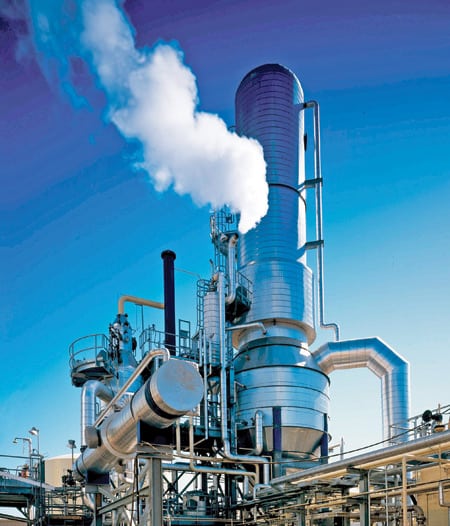
2. Benign effluents. This typical zero-liquid-discharge (ZLD) system at a combined-cycle plant produces only reusable water and a solid cake suitable for disposal in a landfill. Courtesy: HPD
Evaporators and crystallizers operate by transferring latent heat from condensing steam across a tube surface to cause a liquid at its boiling temperature to partially vaporize. But because the steam cycle in a power plant is in precise balance, steam is usually not available for use by a ZLD system. Instead, most power plant ZLD systems use an electric motor-driven heat pump in a technique called mechanical vapor recompression (MVR) to drive the evaporation process (Figure 3).

3. Steam substitute. Mechanical vapor recompression (MVR) is used to drive the evaporation process in a ZLD system when an external steam supply is not available. Source: HPD
External steam, often from a dedicated start-up electric boiler, is used only at cold start-up to heat the equipment and bring the wastewater to the boiling temperature. Once the wastewater begins to boil inside the evaporator, an electrically driven compressor is started. The water vapor evaporated from the wastewater is compressed, raising its pressure and temperature. The hotter compressed water vapor flows to the heating side of the evaporator tubes, where it condenses and transfers its latent heat across the tube wall. That causes more water to evaporate, completing the cycle. The condensed water evaporated from the wastewater is pumped from the evaporator as distilled water (distillate).
Falling-film evaporators/brine concentrators have vertical tube bundles that use some sort of device to distribute the wastewater at its boiling temperature as a thin film around the inside surfaces of the tubes. This film flows uniformly down the entire length of the tube, and as heat is transferred across the tube wall from the condensing steam on the other side, the film boils. Water vapor is released into the core of the tube and mixes and flows with the liquid film.
Next, separate the vapor
Because power plant wastewaters (including FGD purge water) are often saturated with gypsum, the brine concentrator is “seeded” with calcium sulfate to prevent the deposition of low-solubility calcium salts on the tube surfaces as scale. Scaling is prevented by preferential precipitation of low-solubility calcium salts on the seed crystals rather than on the tubes (Figure 4). In a falling-film evaporator, a vapor separator with an integral mist eliminator is attached to the lower end of the evaporator’s tube bundles to help separate the water vapor from the wastewater (Figure 5). The two subsystems ensure that only clean, dry vapor enters the compressor, reducing the risk of its erosion and corrosion by droplets of brine carried over with the vapor. Mist elimination also ensures the distillate’s purity. A well-designed falling-film evaporator will produce distillate with less than 5 ppm TDS.

4. Scale buster. Seeding a falling-film evaporator avoids deposition of calcium salts on the tube surfaces of a brine concentrator. Source: HPD
5. Corrosion controller. Eliminating the mist from the vapor separated by a falling-film evaporator dries the input to the compressor, reducing the potential for corrosion and erosion. Source: HPD
The falling-film brine concentrator with seeding and MVR can now be integrated into a system (Figure 6). A plate heat exchanger recovers heat from the outgoing distillate, making it available to preheat the feed. The feed is typically acidified to eliminate residual alkalinity, and a deaerator is included to remove CO2 and dissolved oxygen from the feed. That reduces the potential for corrosion and scaling in the evaporator vessel.

6. A complete ZLD system. Here, the brine concentrator evaporator of Figure 5 is integrated with seeding and MVR subsystems. The system produces concentrated brine for crystallization. Source: HPD
Then, concentrate the solids
Forced-circulation crystallizers (Figure 7) are the type most often used in power plant wastewater applications. Condensing steam normally provides the energy to evaporate water from waste brine, but in this type of evaporator the brine is forced through the heater tubes by a recirculation pump at high velocity. Flooding the tubes prevents evaporation from occurring inside them. The high velocity of the brine and the suppression of boiling in the tubes prevent scale from forming on the crystallizer’s tube surfaces.

7. Crystal clear. A forced-circulation crystallizer with MVR and solids dewatering uses a compressor and recirculation to produce recovered water and solids for disposal. The feed at bottom left comes from the brine concentrator of Figure 6. Source: HPD
Evaporation occurs when the circulating brine flash boils in a separate vapor body. Nucleation and growth of salt crystals that have exceeded their solubility also occur there. As in the evaporator, a mist eliminator installed in the vapor body separates droplets of brine from the water vapor, protecting the compressor from corrosion and erosion and ensuring the purity of the distillate.
Depending on the TDS concentration maintained in the scrubber, a falling-film brine concentrator can typically concentrate FGD purge water five to 10 times before running up against the limitations imposed by the elevation of boiling point and the solubility limits of the sodium salts. The system reduces the water content of the wastewater by 80% to 90%, so for every 100 gpm of feed, 10 to 20 gpm of concentrated brine is discharged and 80 to 90 gpm of distilled water is produced for reuse in the power plant.
Ordinarily, the concentrated brine would be sent to a forced-circulation crystallizer to evaporate the remaining water and precipitate and dewater the solid salts. However, the solubility of the calcium and magnesium chloride salts that dominate the content of FGD wastewater is so high that it is usually impractical to try to precipitate these salts in a forced-circulation crystallizer. It can be done, but the boiling point of the solution is too high to use MVR, so high-pressure steam must be supplied. What’s more, because the calcium and magnesium chloride are acidic salts that are extremely corrosive at the temperatures and concentrations required to crystallize them, any crystallizer equipment that comes in contact with the brine must be made of very expensive noble alloys such as palladium-alloyed titanium and high nickel-chrome-molybdenum alloys.
There are some cases in which a brine crystallizer may not be economically feasible. Some power plants have considered evaporating their FGD wastewater by a brine concentrator and disposing of the resulting concentrate stream on-site either along with ash or in a separate surface impoundment. Others have considered using spray drying to remove the remaining moisture from the concentrate, producing a dry product suitable for disposal in a landfill or coal mine. It should be noted that because a spray dryer will require a fuel oil or natural gas supply, it also will likely need an air permit. In addition, the dried salt residuals produced are strongly hygroscopic, so they must be bagged quickly to keep them from absorbing moisture from the atmosphere before sending them off for disposal. Other methods of drying the brine concentrator blowdown are possible. They include the use of flakers, prilling towers, and other methods common to the production of calcium and magnesium chloride salts.
Making salt water
Many of the challenges of designing an FGD wastewater treatment process based on evaporation are related to the basic chemistry profile of wastewater. Calcium and magnesium chloride salts are difficult to crystallize and highly corrosive.
To avoid both problems, FGD wastewater can be pretreated using conventional lime-soda ash softening. Slaked lime (calcium hydroxide, Ca(OH)2) and soda ash (sodium carbonate, Na2CO3) are used as reagents in the pretreatment step along with small quantities of ferric chloride and polyelectrolyte to enhance the separation of suspended solids. Adding lime slurry to the wastewater increases the calcium ion concentration, which reduces the gypsum supersaturation and in turn the scaling potential of the wastewater. It also raises the pH so that magnesium hydroxide precipitates. Soda ash is added in a separate reaction tank to precipitate the calcium as calcium carbonate. The net result of the softening process: Sodium ions are substituted for most of the calcium and magnesium ions, so the softened FGD wastewater becomes mainly an aqueous solution of sodium chloride.
Another possibility is to use a conventional water-softening process, producing a ZLD system similar to those currently in use at power plants to treat cooling tower blowdown. Sodium chloride can be readily crystallized in a conventional forced-circulation crystallizer. Although salt is corrosive, its use requires less use of noble materials of construction such as super-austenitic and super-duplex stainless steels.
Future system design
Although power plants have used evaporation for decades to eliminate their discharges of cooling tower blowdown, the evaporation of FGD purge water is a much more recent application with only a few installations and very little operating experience. However, some evaporator suppliers have experience in evaporating calcium, magnesium, and sodium salts that is directly applicable to the evaporation of FGD wastewater. Evaporation is a treatment method that will be considered more often in the future, given the inevitable tightening of limits on air and water discharges from all power plants, the size of the existing U.S. coal-fired fleet, and the prospects for its future expansion.
A plant’s decision about which treatment method to use must take into account its capital and operating costs and other site-specific factors. Due to the current dearth of ZLD system operating experience on FGD wastewater, plant designers, builders, and owners considering a ZLD process should closely examine a prospective supplier’s bench and pilot-scale testing capabilities for calcium, magnesium, and sodium chloride evaporators. A robust system is also important to look for. Do your homework before you buy to avoid costly equipment failures and even more costly losses of generation revenue.
—William A. Shaw, PE ([email protected]) is a senior process engineer for HPD, a Veolia Water Solutions & Technologies company based in Plainfield, Ill.