Air heater leakage: Worse than you think
Rotary regenerative air heaters capture and recycle about 60% of the heat energy exiting the boiler—energy that would otherwise go up the stack. For a 500-MW coal-fired plant, the recycled energy amounts to about 1.5 billion Btu per hour, and reusing it reduces fuel consumption by about 1,500 tons per day.
Although most performance engineers acknowledge that the air heater is among the most important contributors to a plant’s thermal efficiency (perhaps second only to the condenser), many are unaware of the extent of air heater performance problems and their impact on plant operation and efficiency. That impact often is grossly underestimated by a too-narrow definition of air heater leakage in a procedure commonly used to measure it.
The "official" definition of air heater leakage is: "The weight of air passing from the air side to the gas side. It is assumed [italics mine] in calculations to leak directly from the air inlet to the gas outlet." The industry uses this narrow definition because direct leakage is the only kind that can be easily measured in practical terms. However, use of this inaccurate definition produces the erroneous conclusion that the only negative impact of air heater leakage on plant performance is the increase in fan power needed to pump the leaking air. Although a higher fan power requirement is significant (as much as 3 MW per unit), it’s only part of the story.
Underestimating air heater leakage is a shame, because reducing it is relatively inexpensive and provides a big performance bang for the buck. Properly sealing an air heater can improve (reduce) a plant’s heat rate by up to 75 Btu/kWh, increasing power production and revenues as a result.
Excessive air heater leakage can cause any or all of the following additional problems, to name just a few:
- Severe degradation of the performance of downstream air pollution control equipment (electrostatic precipitators, baghouses, and scrubbers).
- Lowered primary air temperatures and consequent reduction of coal mill capacity—particularly in the case of wet coals and Powder River Basin coals.
- Increased potential for mill fires or explosions.
- Load limitations and missed power sales opportunities due to inadequate fan capacity, especially during warm weather.
- Increased NOx production and loss-on-ignition.
- Poor flame stability at lower load and unattached flame ignition points, as well as flame pulsation.
- Excessive desuperheating due to increased convective heat transfer caused by increased mass gas flow.
- Increased heat rate and air heater plugging.
- Increased rate of cold end air heater basket corrosion.
With so much at stake, how can plant engineers be sure their air heater leakage measurements are correct? This article explains ways to be sure and provides steps that can be taken to reduce leakage to acceptable levels.
Why regenerative air heaters leak
Regenerative air heaters capture the heat in boiler exhaust gases by passing them over heat-adsorbing metallic elements. The elements are continually rotated so that they alternately contact the heat gases and cool inlet air produced by the plant’s forced-draft fans. The captured heat is released into the cooler air and cycled back into the boiler.
It’s extremely difficult to seal these types of heaters because their large diameter (up to 60 feet across) and the large temperature difference between their hot and cold sides (about 400 degrees F) together produce dynamic thermal distortion of the rotor. It’s not uncommon for the outer edges of a large, hot air heater to "droop" (or "turn down") by 2 inches or more, compared with a cold condition. Accordingly, there is no existing technology that can seal an air heater 100%.
Underestimating and overspending
The percentage of air heater leakage corresponds to the percentage of total fan airflow bypassing the air heater (either entering or leaving the boiler). Shockingly, leakage rates approaching 50% have been measured in some air heaters, and leakage rates around 20% are commonly accepted as "the best we can do" by many performance engineers.
These numbers are so large that some plants have spent millions of dollars installing larger fans to compensate for high air heater leakage. Even worse, because most of the excess flow makes its way past the air heater and reaches air-pollution control equipment, high leakage rates also can significantly increase the capital and operating costs of scrubbers, baghouses, fabric filters, and the like.
Yet when plant engineers are asked about their air heater leakage, many report rates well below actual levels. On the surface, it may appear that the reported rates are properly measured and calculated. But experience indicates that—when measured properly using ASTM and ASME standards—actual leakage rates are far greater than those assumed by "approximation" measurement techniques. These include calculations done by performance-measurement systems fed data from permanently installed O2 monitors or from manual O2 traverses—which "shortcut" ASTM standards.
Finicky formula
To understand why popular measurement methods can lead to gross underestimation of air heater leakage, consider the method used to calculate the parameter. The accepted method for determining the amount of leakage from an air heater is to measure the oxygen levels at the inlet and outlet of its gas side. For simplicity’s sake, here’s an abbreviated version of the formula:

So, if a plant with permanent O2 monitors measures an O2 level of 2.75% at the inlet of the air heater and 5.5% O2 at the outlet, the calculated leakage would be 17.9%. However, if the number of sample ports is insufficient (a common shortcoming at both inlet and outlets), the measurement of outlet O2 would be erroneous. A more-complete and more-accurate multipoint traverse could indicate an actual O2 level at the inlet of just 0.25%. Plugging this much-smaller "O2 in" number into the numerator of the equation given above would produce a leakage "measurement" of 34%—almost twice the previously calculated level.
Lest you think plant engineers would be unlikely to make such a huge error, take a look at Figure 1, which was originally published in an article on Alabama Power’s Gorgas Steam Plant in the June 2005 issue of POWER. The figure, which shows the dramatic variation in actual O2 distribution at the economizer outlet (air heater inlet), reveals exactly that amount of mismeasurement of O2 at the air heater inlet. Even larger measurement errors are common at air heater outlets.
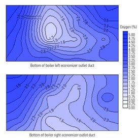
1. All over the lot. O2 distribution at the inlet of the exhaust side of a rotary regenerative air heater. Courtesy: Innovative Combustion Technologies Inc.
In measuring O2 at the inlet and outlet of the air heater, it is critical to realize that both the O2 distribution and the velocity distribution can deviate widely from test point to test point. A velocity pressure reading must accompany each O2 reading to give accurate results. Velocity pressures at the outlet of the air heater can even be negative at some points, compounding the difficulty of obtaining accurate readings.
In addition, the locations of sample points must reflect the fact that a large share of leakage from an air heater exits the unit in close proximity to the duct walls. The recommended placement of sample points is at least one measurement for every 4 square feet of duct area, with the initial and final points within 9 inches of the duct walls. Although very few power plants go to this extent to measure their air heater leakage, the magnitude of the performance gains achievable from an adequate assessment of the problem can easily justify the expense of an accurate test.
Variations in O2 readings of as little as +/- 0.2% at the air heater inlet and outlet can lead to gross errors in air heater leakage calculations. Permanently installed O2 monitors are incapable of this level of accuracy, and—as Figures 2 and 3 make clear—the likelihood of being able to position permanent monitors to give representative readings is extremely remote. The two figures, using data from actual measurements at the outlet of the air heater of a 600-MW coal-fired unit, graphically demonstrate the wide parametric variations commonly encountered during attempts to accurately measure air heater leakage.
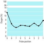
2. Curved air. Flue gas oxygen distribution at the outlet of the air heater of a 600-MW coal-fired unit. Source: Paragon Air Heater
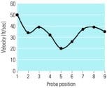
3. Speed vs. location. Flue gas velocity distribution at the air heater outlet of the same plant. Source: Paragon Air Heater Technologies
Downstream impact
Air heater leakage is rarely associated with the performance of downstream air pollution control units. But the former definitely impacts the latter. In the case of baghouses, a reduction in overall airflow of 20% (by reducing air heat leakage) produces a better air-to-cloth ratio, reducing pressure drop and bag breakage. The same beneficial effects are produced if higher-temperature air enters the baghouse; this can be accomplished by reducing the amount of cold air bypassing the air heater’s radial seals and entering the exhaust gas.
The benefits of reduced air heater leakage on the collection efficiency of electrostatic precipitators (ESPs) are even greater. The particulate-capture efficiency of an ESP unit rises and falls exponentially with its specific collection area (SCA)—a ratio of the area of its collecting electrode to the gas flow rate at its inlet. Less leakage means lower gas flow rates and higher SCAs.
Higher SCAs are important because most ESPs now must operate at about 99.5% efficiency to achieve regulatory compliance. The common industry practice for improving ESP collection efficiency is to spend millions or tens of millions of dollars on additions and/or upgrades. The same level of improvement may be achievable for a fraction of the cost, by reducing air heater leakage.
An ounce of maintenance, a pound of cure
By now, it should be clear that air heater leakage adversely affects many areas of plant operation, not just fan capacity. Due to that plantwide impact, maintenance of air heater sealing systems should receive top priority.
Engineers should remember that because air heater seals and their mating surfaces naturally wear, they are designed to be replaced. Trying to save a few pennies by extending the life of worn or obsolete seals is "pound-foolish."
A simple and cost-effective way to improve air heater sealing is to stop using traditional, "standard type" air heater seals. Because they are little more than strips of thin-gauge steel, standard seals cannot seal tightly and often are blown over or damaged by the high differential pressures produced by the installation of air pollution control equipment downstream.
By contrast, today’s generation of high-performance air heater seals has proven able to reduce air heater leakage by 50% or more, compared with standard seals. Some newer seals (Figure 4) use a bellows to produce a spring force that keeps the seal in contact with its mating surface (the sector plate) over a wide range of differential pressures and rotor turndowns. Others, called interlocking circumferential seals, are used on the perimeter of the air heater’s rotor. They reduce bypass leakage, and their structure is designed to resist the type of damage suffered by standard design seals during rotor turndown.

4. Spring time. A high-performance bellows seal in flex position, contacting the sector plate. Courtesy: Paragon Air Heater Technologies
To sum up . . .
Due to thermal expansion and contraction, all rotary regenerative air heaters have dynamic leakage gaps that widen and narrow with load.
Air heater leakage has a huge effect on a power plant’s heat rate, required fan capacity, coal drying and mill performance, precipitator/scrubber efficiency, and the like. Many plants lose the chance to sell hundreds of megawatt-hours each day due to excessive air heater leakage alone. During periods of peak demand, the lost daily revenue may amount to as much as $100,000.
Despite the severe, negative economic impact of air heater leakage, most plants continue to grossly underestimate their leakage because they don’t know how to measure it accurately. Leakage measurements must be based a multipoint traverse of both sides of the air heater and include measurements of both O2 and flue-gas velocity levels. Finally, the test points must be located to cover high-leakage sectors (typically, those very close to duct walls).
Relying on existing continuous O2 monitors will necessarily produce the false conclusion that air heater performance is much better than it actually is. The continuous performance monitoring systems that most plants rely on today can do a great job of mathematically calculating leakage, but they cannot overcome the inaccuracy of data provided by continuous O2 monitors. In this case, the adage "garbage in, garbage out" certainly applies.
The cure for excessive air heater leakage is a straightforward, two-step process. First, be sure you’re accurately measuring the actual amount of leakage present, and then tighten up your air heater sealing system by installing modern, high-performance seals.